Pump types
Several pump types can be specified in MIKE+:
- Constant flow pumps
- Constant speed pumps
- Variable speed pumps.
Constant flow pumps
This is the simplest way of modelling pumps. In this case the pump will discharge the same constant flow Q at any time when the pump is switched on. Eventually with the variation as defined during acceleration or deceleration periods.
When specifying a constant flow pump, set the Speed to ‘Constant’ and choose ‘Constant’ in the pump type field. In the Capacity tab type the constant flow value set for
Note
'Constant flow' pump is different from 'Constant speed' pump. The later may have varying discharge.
Constant speed pumps
When defining pumps in MIKE+ models for sewer and drainage systems it will most commonly be pumps with a pump curve of type "Q, dH". The actual pump discharge Q will be a function of the actual pressure difference dH between the pump wet well and the receiving point in the model. The pump curves for this type of pumps will in general be as shown in the figure below.
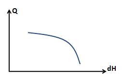
Figure: Typical example of pump curve
Pump curves are defined in MIKE+ by tabulating the curve under Curves and Relations. This can be done by selecting representative points on the pump curve as shown in the next figure. Information about pump curves are typically provide by the manufacturer of the pumps.
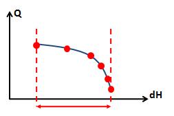
Figure: Tabulating the curve
When a pump curve is tabulated like this and used in the simulations executed with the MIKE 1D Engine, then the pump is allowed to operate within the range of the dH values in the table. At any time during the simulation the MIKE 1D Engine will compute the actual dH and determine the corresponding Q value from the table, resulting in the actual duty point position for the pump.
As a standard feature the MIKE 1D Engine will stop the simulation with an error message if the hydrodynamic conditions result in an actual dH value outside the range of the pump curve table.
Variable speed pumps
When applying variable speed pumps the manufacturer typically provides a set of pump curves describing the pump capacity at various percentages of maximum rotation speed or maximum power input. You may have a set of curves available as show in the figure below.
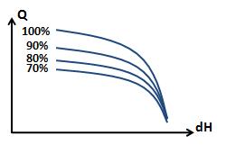
Figure: Pump curves at various percentages of maximum rotation speed or maximum power input
It is also found that variable speed pumps cannot be regulated over the full range between 0% and 100%. Instead the regulation may be in the range of 70% to 100% as indicated in the figure above. Search for specific information available for the pumps applied at the pumping stations being modelled.
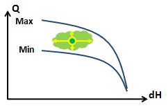
For simplicity in the modelling the actual method of varying the pump capacity is not considered. It is not directly related to the actual number of rotations per minute (RPM) or the actual electrical power input. In the modelling we only consider the pump capacity as varying between a pump curve corresponding to the minimum speed and a pump curve corresponding to the maximum speed.
For variable speed pumps the two pump curves are defined as 'RPMmin' and 'RPMmax' pump curves. For constant speed pumps only the 'RPMmax' pump curve is applied.
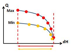
Figure: The RPMmax and RPMmin pump curves
When the MIKE 1D simulation is executed it is the standard condition that the simulation will stop and give an error message if the conditions exceed the range for the dH value in the pump curve table. This applies both for the 'RPMmax' and the 'RPMmin' pump curve.
Operation of variable speed pumps
In the Regulation tab it is possible to regulate the pump to maintain a water level in the wetwell. The corresponding 'Wetwell WL Setpoint' must be specified when using this option.
When a variable speed pump is in operation during the simulation with the MIKE 1D Engine the duty point will move between the two pump curves depending on the actual conditions. The actual flow is determined by using a PID function which will attempt to control the water level at the wet well to stay at the specified set point value.
The discharge Q determined by the PID function and the dH found by the actual hydraulic conditions defines the duty point. This may vary in the area between the two pump curves.
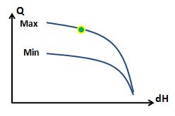
Eventually the conditions may result in the duty point ending up on one of the pump curves. If the PID regulation sets the discharge Q to a value higher than the limitation by the 'RPMmax' pump curve at the given dH condition, then the discharge will be defined by the pump curve. As a consequence the water level in the wet well will rise above the defined set-point value.
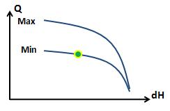
If the inflow to the pumping station is low, then the operation of the pump may result in an actual duty point located at the 'RPMmin' pump curve. In this case the water level at the wet well will drop below the defined set-point value. Eventually the water level will reach the stop level defined for the pump and the operation is switched off
The MIKE 1D engine will pump as much flow available to discharge in the structure, which means that the pump works continuously during the simulation if there is lack of water in the pump wet well then the pump will discharge a flow of zero during those lapses but will not be forced stop.
The hydrodynamic network simulation provides a simulation summary report at the end of the computation. The summary for the pumps will show the number of pump starts during the simulation.
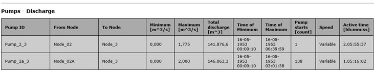
Figure: Summary of pump starts during simulation
The pump flow continues during the specified deceleration period by a linear decrease to zero flow. During this time interval the water level in wet well may eventually drop to the bottom of the wet well during a single time step
The 'Pumps - Discharge' section is only shown in the summary report if 'pumps' has been selected in the “Network Summary” under Result Specifications.
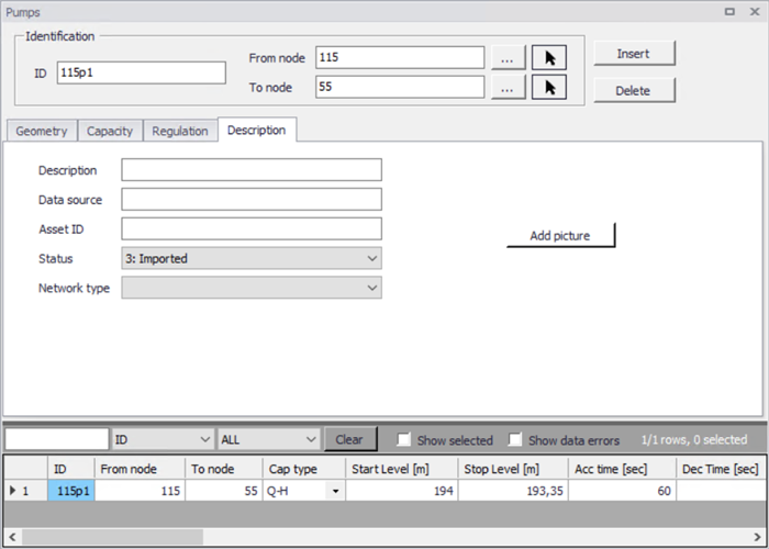
Figure: Pumps description tab
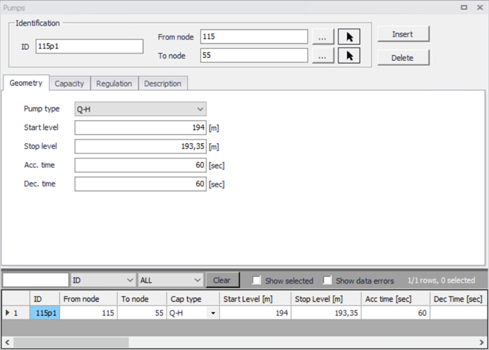
Figure: Pump geometry tab
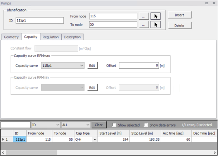
Figure: Pump Capacity tab
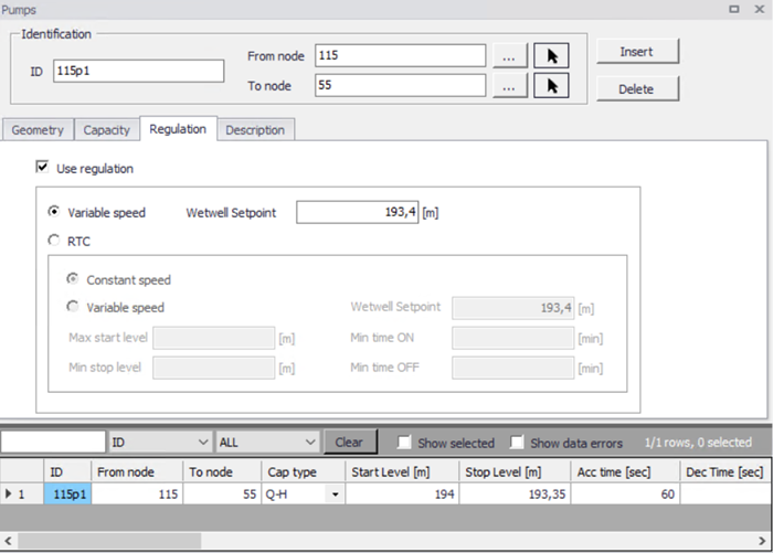
Figure: Pump regulation tab
A pump is characterised by the 'Start Level' and 'Stop Level', acceleration and deceleration time, an offset and a capacity curve. The capacity curve is specified in the Curves and Relations section. The capacity curve can be specified as a 'Capacity Curve QH' relation (for screw pumps) or as 'Capacity Curve QdH' relation (for differential head pumps), where 'H' is the absolute water level in the pump's wet well (at 'Location'), and 'dH' is the water level difference between the 'To node' and the 'From node' location.
A pump type with a 'Capacity Curve QH' relation is named a screw pump, while a pump type with a 'dH-Q' relation is named a differential head pump.
If an offset is specified this will be added to the capacity curve relation.
Pumps are per default static (No Control) but can be regulated through control rules. Selecting the ‘Control rules’ radio button enables the control of start and stop levels or pump flows during the simulation.