LID Deployment Editor
The LIDs are assigned to a catchment by means of the LID Deployment editor.
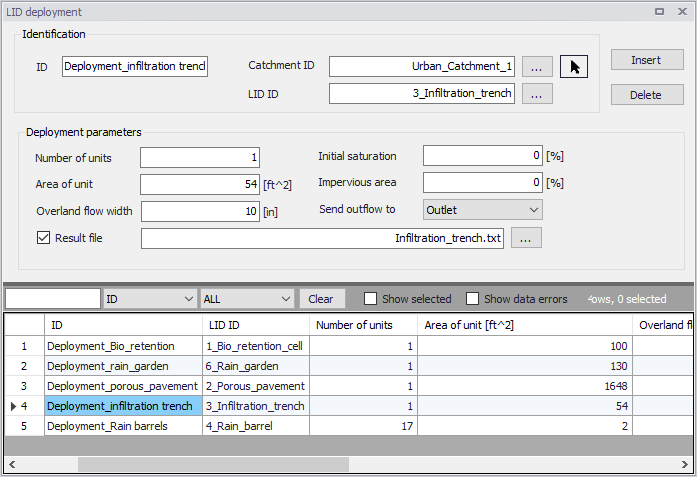
Figure: The LID Deployment editor
The input data is organized into the following groups:
- Identification
- Deployment Parameters.
Identification
Each LID is linked to a LID Deployment ID i.e. each deployment represents a LID deployed on a single catchment in a specified number of units.
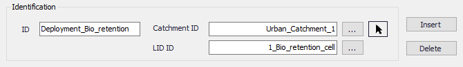
Figure: The LID Deployment Identification group
| Edit Field | Description | Used or required by simulations | Field name in data structure |
|---|---|---|---|
| ID | LID deployment ID | Yes | MUID |
| Catchment ID | ID of catchment in which the LID is deployed/located (see Catchments editor) | Yes | CatchID |
| LID ID | ID of LID to be deployed (see LID Properties editor) | Yes | LidID |
Table: Edit fields in the Deployment Identification group (mss_LIDusage)
Deployment Parameters
It is possible to specify the size (i.e. area) of the individual LID structure, the size of the catchment´s impervious and pervious areas that are funneled into it and the number of LID units of a certain type in the catchment. Furthermore, level of initial saturation and routing width for overland flow can be specified.
It is also possible to select any node or catchment to which the drain flow is routed to. If this remains empty, this drain flow goes to the same outlet as the containing catchment's outlet.
It is also possible to control whether the outflow from the LID structure should be routed to the pervious area of the containing catchment, or to its outlet. If the drain flow is routed to another location than the containing catchment's outlet, only the surface outflow will be routed; if the drain flow is routed to the containing catchment's outlet, both surface and drain flow will be routed.
For each LID deployment, a result file can be generated containing time series of relevant variables (fluxes and storages). This result file is in the TXT time series format.
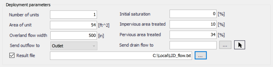
Figure: The LID Deployment Parameters group
| Edit Field | Description | Used or required by simulations | Field name in datastructure |
|---|---|---|---|
| Number of Units | Number of replicate LID units deployed within the catchment | Yes | ReplicateNumber |
| Area of Unit | The surface area devoted to each replicate LID unit (sq. ft or sq. m). | Yes | Area |
| Overland Flow Width | The width of the outflow face of each identical LID unit (in ft or m). This parameter only applies to LID processes such as Porous Pavement and Vegetative Swales that use overland flow to convey surface runoff off of the unit. (The other LID processes, such as Bio-Retention Cells and Infiltration Trenches simply spill any excess captured runoff over their berms.) | Yes | Width |
| Initial Saturation | For Bio-Retention Cells this is the degree to which the unit's soil is initially filled with water (0 % saturation corresponds to the wilting point moisture content, 100 % saturation has the moisture content equal to the porosity). The storage zone beneath the soil zone of the cell is assumed to be completely dry. For other types of LIDs it corresponds to the degree to which their storage zone is initially filled with water | Yes | InitSat |
| Impervious Area treated | The percent of the impervious portion of the catchment's non-LID area whose runoff is treated by the LID practice. (E.g., if rain barrels are used to capture roof runoff and roofs represent 60% of the impervious area, then the impervious area treated is 60%). If the LID unit treats only direct rainfall, such as with a green roof, then this value should be 0. If the LID takes up the entire subcatchment then this field is ignored. | Yes | FromImp |
| Pervious Area treated | The percent of the pervious portion of the catchment's non-LID area whose runoff is treated by the LID practice | Yes | FromPerv |
| Send Outflow to | Select whether to send the outflow from the LID onto the subcatchment's pervious area, or the subcatchment's outlet. An example of where this might apply is a rain barrel whose contents are used to irrigate a lawn area. This field is ignored if the LID takes up the entire subcatchment. | Yes | ToPervNo |
| Send drain flow to | Select any node or catchment to which the drain flow is routed to. If left empty, the drain flow goes to the same outlet as the containing catchment's outlet. | Yes | DrainTo |
| Result File | Activate this option to generate a detailed result file for the LIDs | Yes | RptFileNo |
| (Filename input box) | The name of an optional TXT file where detailed time series results for the LIDs will be written | Yes | RptFileName |
Table: Edit fields in the LID Deployment Parameters group (mss_LIDusage)
LID Deployment Result File
A text result file (.txt) may be generated for each deployed LID structure. The file includes time series of relevant variables for the LID structure in terms of inflow, flow between layers, storage levels in various layers and output from the structure to the native soil.
If the user does not activate this option, the only visible outputs from the runoff simulation including LIDs are the changed (reduced) runoff hydrographs, caused by infiltration loss and storage in the LID structure, and a LID Performance Summary in the simulation summary file.
The contents of the text file depend on the actual LID type. In the figure below, an example file for porous pavement is presented. Columns contain time series values for processes in the porous pavement.
Note
The flow inside the LID structure and the drain flow are reported as intensities based on the LID area. In cases where the collecting area is bigger than the LID area, the reported intensities will not be comparable with rainfall and evapotranspiration intensities, which are given as model boundary conditions. In order to make the comparison possible, the reported flow intensities must be scaled down by the ratio between the LID area and the collecting area.
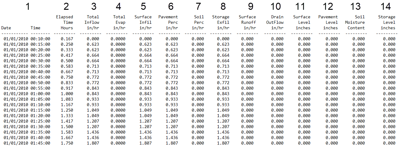
Figure: Example of a result report DFS0 file per deployment (a porous pavement control)
- Date/Time: Calendar time for the simulated time steps
- Elapsed Time [T]: Time elapsed relative to simulation start
- Total Inflow [L/T]: Inflow to the LID unit given as a multiple of the rain intensity and the collecting area outside LID/LID area. It is the run-on from the collecting area outside the LID and rain on top of the LID unit. The run on represents the net rain on the impervious collecting area, i.e. with initial losses subtracted.
- Total Evap [L/T]: Evaporation based on given Climatology parameter specified by the User valid for the catchment as well as for the LID unit.
- Surface Infil [L/T]: Infiltration from the surface layer to the pavement layer.
- Pavement Perc [L/T]: Flow from the pavement layer to the next layer i.e. storage layer or optional soil layer.
- Soil Perc [L/T]: Flow from the optional soil layer to the storage layer.
- Storage Exfil [L/T]: Infiltration from the storage layer to the surrounding soil.
- Surface Runoff [L/T]: Represents overland flow for vegetative swale s or overflow for other LIDs
- Drain Outflow [L/T]: Water flow through the optional underdrain.
- Surface Level [L]: accumulated water on the surface expressed as the water height on the surface. Maximum value is the specified surface storage depth/berm height.
- Pavement Level [L]: Accumulated water depth in the pavement layer. Maximum value is the pavement thickness.
- Soil Moisture Content []: Presented as a fraction relative to the total volume of the optional soil layer. Corresponds to the water that is held in the spaces between soil particles. Maximum soil moisture (i.e. full saturation) is equivalent to the specified soil porosity.
- Storage Level [L]: Accumulated water in the storage layer expressed as the water height in the storage. Maximum value is the storage height.
LID Performance Summary
The LID Performance Summary is provided as part of the overall simulation summary file. The summary reports the overall storage/loss depths and volume balance for each LID deployment.
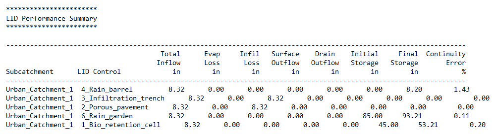
Figure: Example of a LID Performance Summary