Valve Criticality
The Valve Criticality tool allows analysis of a valve from the valve layer to determine which valves need to be closed in order to replace the selected valve. This tool helps you to understand the important of isolation valves and assists you in the valve maintenance and replacement program.
Launch the Valve Criticality tool from the WD Analysis Toolbox in the 'WD Network' tab of the ribbon.

On the Valve Criticality dialog that appears, define the layers containing your pipe network and valves. Valve criticality can operate in two modes:
- Interactive mode: Allows you to inspect valves one by one by pointing and clicking on a valve.
- Automatic mode: Allows you to run the tool for selected valves and store the results in the database.
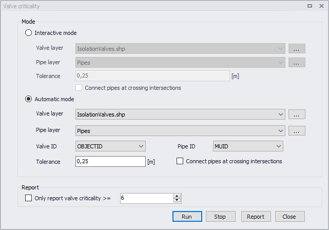
Figure: The Valve Criticality dialog
The Valve Criticality dialog
A list of the Valve Criticality attributes follows, with a short description given for each one.
- Interactive mode: This mode allows you to run the valve criticality analysis in interactive mode when you click the valve in the Map and the program finds substitute valves.
- Automatic mode: This mode allows you to run the valve criticality analysis in automatic mode for any number of selected valves.
- Valve layer: This data entry allows you to select the GIS layer with valves (typically isolation valves) that will be used in the valve criticality analysis. Please note, that in order to select valve layer in this data entry, the valve layer needs to be already added to the Map layers beforehand.
- Pipe layer: This data entry allows you to select the layer with pipes. It could be a model pipes layer or GIS pipe layer. Please note, that in order to select a GIS pipe layer in this data entry, the layer needs to be already added to the Map layers beforehand.
- Tolerance: This data entry allows you to define the spatial tolerance that will be used to track the pipe network connectivity.
- Connect pipes at crossing intersections: When the pipe layer is defined from a GIS layer, this option allows you to define whether the pipe network connectivity will consider pipes connected whenever they cross each other. In case of a pipe layer from the hydraulic model this option would not be used because connecting pipes require a junction node at their cross connection. However, in case of a GIS layer this option could be required in order to track the connectivity.
- Valve ID: This data entry allows you to define the valve identification ID that will be used by the program for reporting purposes.
- Pipe ID: This data entry allows you to define the pipe identification ID that will be used by the program for reporting purposes.
Running analysis
Click the 'Run' button in order to run the analysis. In case of "interactive" analysis, the valve needs to be selected from the Map window. In case of "automatic" analysis, the program will start analysing all valves and the simulation progress will be displayed in the application status window. The analysis can be interrupted (cancelled) by pressing the Esc key or clicking the 'Stop' button.
Valve criticality results
Results of the Valve Criticality tool are added to the Map where valves are assigned symbols based on the number of substitute valves.
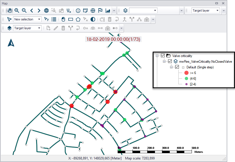
Figure: Example Valve Criticality result plot on the map sizing and coloring valves according to importance/criticality
Valve criticality results include:
- No of closed valves: Number of other valves that need to be closed in order to replace the malfunctioning (selected) valve
- Closed valves: List of such valves
- Closed pipes: List of pipes that are contained within the pipe network area isolated by valves
- Sum length of pipe: Length of such pipe network
Click on the ‘Report’ button to generate a report on these Valve Criticality results.
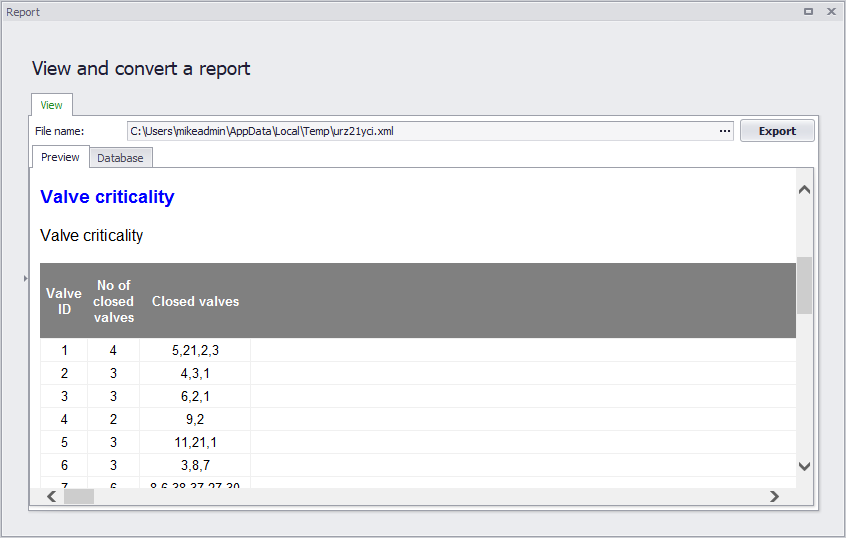
Figure: Example Valve Criticality report