Inlets
Street inlets are curb and gutter openings that convey runoff from streets into below-ground sewers. Drop inlets serve a similar purpose for trapezoidal channels. SWMM computes the amount of flow captured by inlets and sent to the selected sewer nodes using the FHWA HEC-22 methodology.
Street drainage must be represented with a combination of conduits representing streets (i.e. ground surface), and regular sewer conduits below the surface. Inlet structures are then specified on surface conduits to control the flow from the streets to the sewer network. The flow computed through the inlet is diverted from the surface to the selected receiving sewer node, while the exceeding surface flow is transferred to downstream streets.
When an inlet's sewer node reaches its full depth, any excess flow that would cause it to flood is sent back through the inlet and onto the street.
The 'Inlets' editor in MIKE+ defines the inlet structures settings. Once defined in this editor, inlets are then applied to the ground surface network from the Inlets tab in the 'Conduits' editor, on conduits with appropriate shapes (e.g. Street, Rectangular or Trapezoidal).
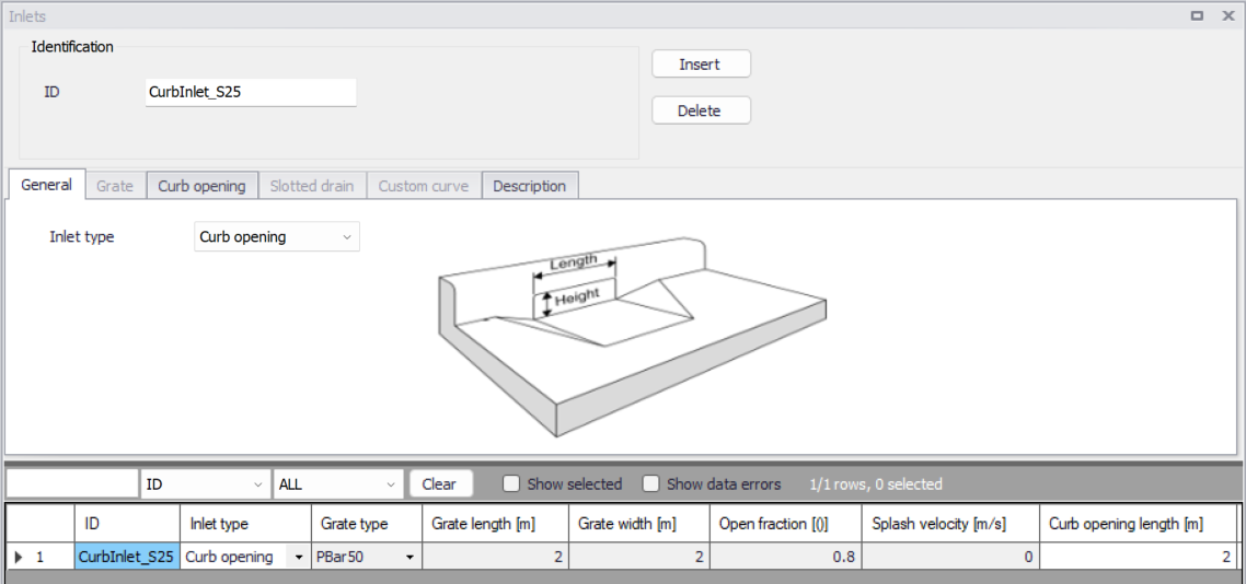
Figure: The SWMM Inlets editor
For each inlet, the inlet type is selected in the 'General' tab. The following types are available:
Drop inlets can only be used with rectangular or trapezoidal channels while the other curb and gutter inlets can only be placed in conduits with Street shape.
A summary of results for each street conduit (maximum flow depth and pavement spread) and for each inlet (percent capture at peak flow, frequency of bypass flow and frequency of sewer system backflow) will appear as a separate Street Flow table in SWMM's Summary Results report.
Notes
- The rim elevations of nodes that receive captured inlet flow do not have to match the invert elevations of the end node of the conduit containing the inlet.
- Two-sided street conduits (that are symmetric about the street crown) use pairs of inlets placed on each curb side of the street.
- For on-grade placement the flow captured by each inlet is determined sequentially, so that the approach flow to the next inlet in line is the bypass flow from the inlet before it.
- Flow captured by inlets is limited by the amount that its sewer node can receive before it floods. If the node has no such capacity remaining then any excess flow that would cause it to flood is sent back through the inlet and onto the street.
- For Kinematic Wave and Steady Flow routing it is recommended that storage nodes be used at the end of inlet conduits that converge at sag points since otherwise any non-captured flow will simply exit the system. This is not necessary for Dynamic Wave routing as any non-captured water will create a backwater effect raising water levels in the adjoining street conduits.
- While the general properties of inlets are specified in the 'Inlets' editor, additional conduit-specific settings are specified in the 'Conduits' editor (e.g. number of inlets of the same design, degree of clogging, maximum flow, etc.).
Grate and Drop grate
The following settings are required to define a grated inlet or a drop grate inlet:
- Grate type: the following designs are available:
- PBar50: parallel bar grate with bar spacing 1-7/8-in on center
- PBar50x100: parallel bar grate with bar spacing 1-7/8-in on center and 3/8-in diameter lateral rods spaced at 4-in on center
- Pbar30: parallel bar grate with 1-1/8-in on center bar spacing
- Curved vane: curved vane grate with 3-1/4-in longitudinal bar and 4-1/4-in transverse bar spacing on center
- TiltBar45: 45 degree tilt bar grate with 2-1/4-in longitudinal bar and 4-in transverse bar spacing on center
- TiltBar30: 30 degree tilt bar grate with 3-1/4-in and 4-in on center longitudinal and lateral bar spacing respectively
- Reticuline: "Honeycomb" pattern of lateral bars and longitudinal bearing bars
- Generic: a generic grate design.
- Length: the length parallel to the street curb
- Width: the grate's width
- Open fraction: the fraction of the grate's area that is open. Only used for generic grates. Values are predetermined for non-generic grates.
- Splash velocity: the minimum velocity that causes some water to shoot over the inlet thus reducing its capture efficiency. Only used for generic grates. Values are predetermined for non-generic grates.
Curb opening and Drop curb
The following settings are required to define a curb opening inlet or a drop curb inlet:
- Length: the length of the opening
- Height: the height of the opening
- Throat angle: the orientation of the curb opening's throat relative to the street surface. The following types are available:
- Vertical
- Horizontal
- Inclined.
Note
For 'Combination' inlets, only the portion of the curb opening that extends beyond the length of the grated inlet contributes to inlet capture efficiency.
Combination
This is a combination of grated and curb opening inlets, hence requiring the same settings to be specified.
Slotted drain
The following settings are required to define a slotted drain inlet:
- Length: the drain's length parallel to the street curb
- Width: the drain's width.
Custom
The custom type of inlet can be used in both streets and channels. Its capture efficiency is described by either a user-defined Diversion curve (captured flow vs inlet's approach flow, typically used for divider nodes) or Rating curve (captured flow vs water depth, typically used for outlet conduits).
For this inlet type, only the curve type and curve ID must be specified. Curves are defined in the 'Curves and relations' editor, where diversion curves must be set with the curve type 'Divider', whereas rating curves must be set with the curve type 'Rating'.