Generic Shapes
The ‘Generic shapes’ editor allows the definition of the conduit’s cross-section, when it is uniform along this conduit.
Generic shapes are created and deleted using the 'Insert' and 'Delete' buttons in the left part of the editor. The shape ID can later be associated with a pipe from the 'Pipes and canals' editor, when its link type is also set to 'Generic shape'.
Generic shapes support open and closed cross sections. The X-Z types are appropriate for irregular cross sections, while H-W are best for symmetric cross sections.
Cross section shapes are classified in five types:
- H-W closed: The shape is described by (h, w) pairs, where 'h' is relative height above the pipe invert level, and 'w' is the corresponding cross section width. The pairs are specified in an upward direction. The last specified (h, w) pair defines the top of the closed cross section.
- H-W open: The shape is described by (h, w) pairs, where 'h' is relative height above the pipe invert level, and 'w' is the corresponding cross section width. The pairs are specified in an upward direction.
- X-Z open: The shape is described by points defined by coordinate pairs (x, z), where 'x' is a distance along the horizontal axis (with the left-most point of the cross section usually starting at x=0), and 'z' is the corresponding elevation. The points are specified in a counter-clockwise direction.
- X-Z closed: The shape is described by points defined by coordinate pairs (x, z), where 'x' is a distance along the horizontal axis (with the left-most point of the cross section usually starting at x=0), and 'z' is the corresponding elevation. The points are specified in a counter-clockwise direction. The first and last points are connected to close the cross section.
- X-Z-R-M open: The shape is described by points defined by coordinate pairs (x, z), where 'x' is a distance along the horizontal axis (with the left-most point of the cross section usually starting at x=0), 'z' is the corresponding elevation, 'R' is the relative roughness and 'M' describes markers. The points are specified in a counter-clockwise direction. This type allows to specify open channel systems to have variable roughness across the cross section.
Markers are used to identify special points within the cross section, like bank levels of the channel.
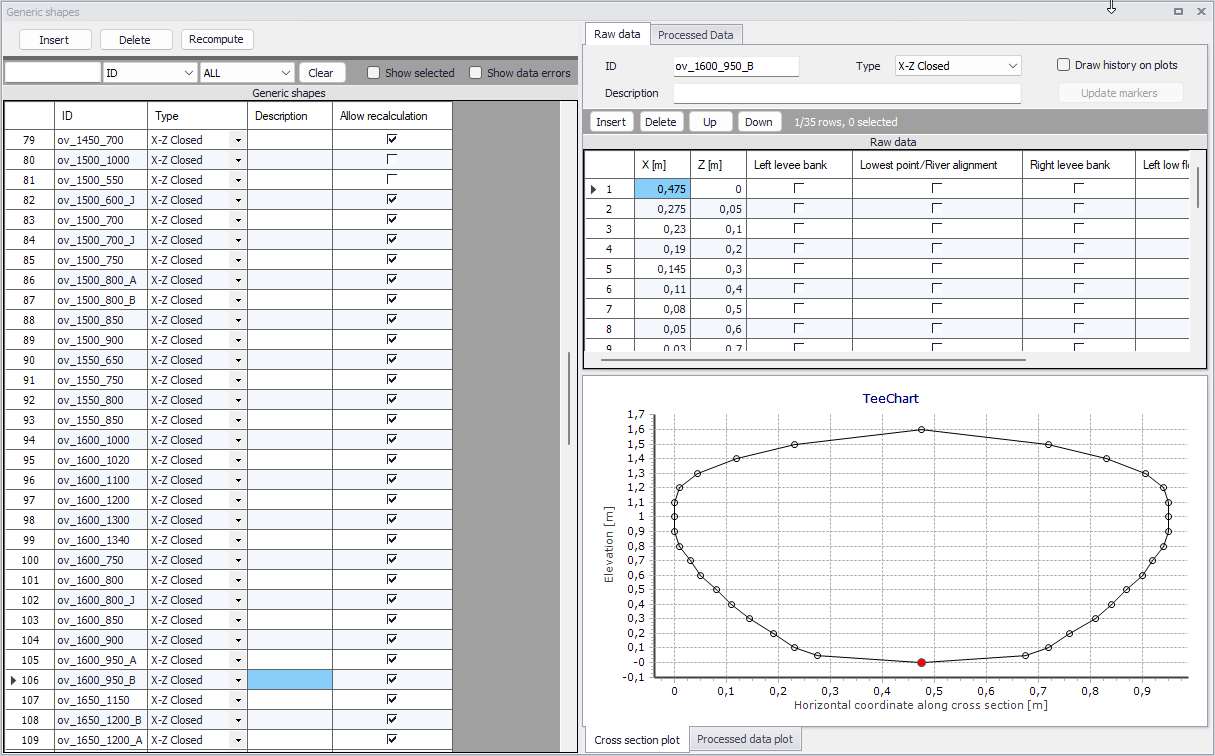
Figure: The Generic shapes editor
The geometrical data of the cross section are specified in the 'Raw data' tab on the right part of the editor, and are shown on the graphical view underneath. If the 'Draw history on plots' option is ticked at the top of the 'Raw data' tab, the plot will show the current shape in black and the previously plotted shapes in grey, for comparison.
For the need of the hydraulic simulation, a table of data is derived from geometrical data in the 'Processed data' tab. This table is mandatory and should be computed using the 'Recompute' button at the top of the tab. After making changes to the geometry in the 'Raw data' tab, these processed data need to be recomputed again to reflect the geometry change.
The 'Recompute' button on the left part of the editor can be used to recompute all shapes at once (or only the selected ones, if any). The 'Allow for recalculate' button in the 'Processed data' tab can be unticked to lock the processed data for individual shapes: this is especially useful to keep some manual changes for specific shapes, while keeping the ability to recompute all other shapes at once.