Create and Update Transects
The Create and Update Transects tool is used for deriving or updating transects data used for Conduits with Irregular cross sections. Transects data describe how bottom elevation varies with horizontal distance over the cross section. These are represented by Station-Elevation value pairs defined on the Transects editor in MIKE+.
Access the tool through the MIKE+ CS Network menu ribbon under Network Editing Tools.
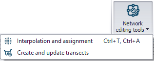
Figure: CS Network Editing Tools
Use the tool proceeding thorough each section of the dialog as follows:
- Method
- Survey Points Settings (depending on the method chosen)
- DEM Settings (depending on the method chosen)
- Input Selection
- Running the Tool and Reporting
Each of the above steps are described in the following sections.
Method
Select the transect editing process to perform on the Method tab page of the dialog. The available operations are:
- Create Transects from Survey Points: Generate transects from survey points in *.shp or *.xyz file formats. This option activates the Survey Points Settings tab page, wherein one defines the file and the attribute from which elevation values are taken.
- Create or Extend Transect from DEM: Generate new or extend existing transects from a DEM raster. Transect data may be derived based on the locations of existing conduits or background features. This option activates the DEM Settings tab page on the dialog.
- Create Transects from Survey Points and DEM: Use both survey points data and a DEM to create or extend transect data. This option activates both the Survey Point Settings and the DEM Settings tab pages on the dialog.
- Update Transects with DEM: Option to make changes to existing Transects using a DEM raster, when, for example, new updated elevation data are available for the study area.
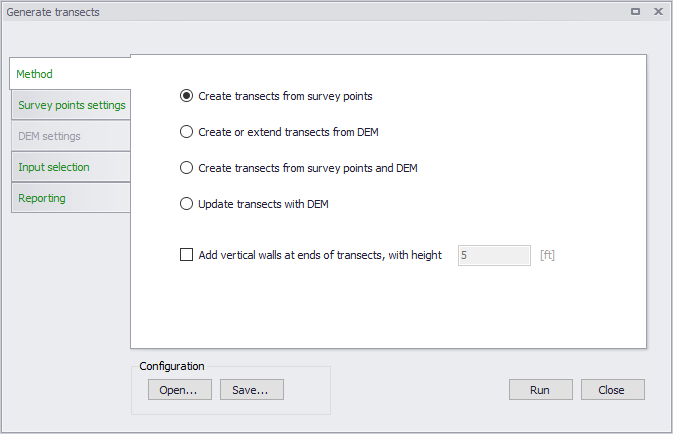
Figure: Method section on the Generate Transects dialog
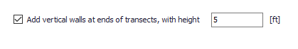
There is also an option for adding vertical walls with a specified height to the ends of created/updated transects. Tick on the ‘Add vertical walls at ends of transects’ option, and define the height of the vertical wall in the input box beside the option.
Survey Points Settings
If the selected method from the previous tab page involves the use of survey points, the survey points data file and parameters related to how data from the file shall be interpreted by the tool are defined on the Survey Points Settings tab page.
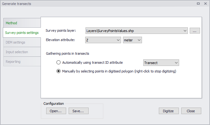
Figure: Survey Points Settings tab page on the Generate Transects dialog
Define the following on the page:
- Survey Points Layer: Choose or load the shape file or *.xyz file to use in the processing from the dropdown list or the ellipsis button, respectively.
- Elevation Attribute: Choose the item from the shape or *.xyz file to use as source of elevation values.
- Gathering Points in Transects: Set how values are obtained and saved as transect data:
- Automatically using Transect ID attribute: Select the attribute in the file that connects the individual survey points to a specific transect. All survey points with the same ID field will be created as one transect.
- Manually by selecting points in digitised polygon: Define a polygon on the Map covering survey points to be used for a transect. Click on the ‘Digitize’ button at the bottom of the dialog to start defining the polygon feature on the Map. Right-click on the Map to end digitizing the polygon. This option creates one transect at a time.
The transect will be created as a straight line through the connected survey points using a least square fit. The individual survey points are projected orthogonal on to the transect line.
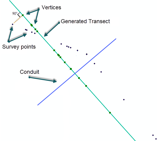
Figure: Survey points are projected onto the transect
DEM Settings
If the selected transect creation method involves the use of DEM data, the DEM raster file and parameters related to how data from the file shall be used by the tool are defined on the DEM Settings tab page.
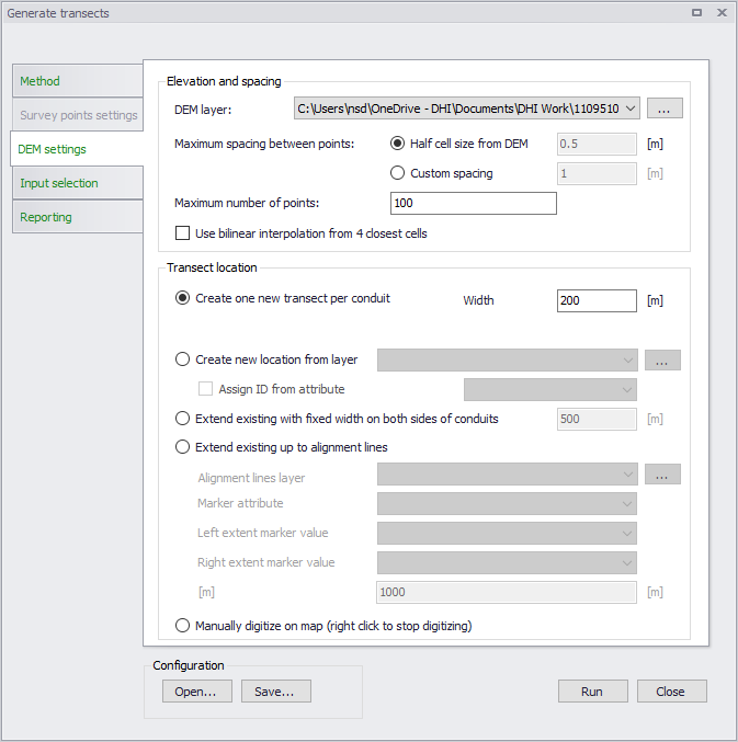
Figure: DEM Settings tab page on the Generate Transects dialog
Elevation and Spacing
Define the following parameters under the Elevation and Spacing group:
- DEM Layer: Define or load the DEM raster layer to use for transects generation. These raster files may be in *.txt, *.asc, *.dfs2, *.tif, or *.tif formats.
- Maximum Spacing Between Points: The maximum spacing between transect points can be user-specified or assumed as half the cell size of the DEM.
- Half cell size from DEM: Half the DEM grid size resolution.
- Custom Spacing: Option to define a spacing for transect point values.
- Maximum Number of Points: Should the specified maximum spacing between points results in more than the allowed maximum points the spacing is increased to obtain the maximum number of points.
- Use Bilinear Interpolation from 4 Closest Cells: Option to use bilinear interpolation when extracting elevation values from DEM cells. If unchecked, the elevation along the transect will be the exact value from the DEM cells that are intersected, whereas if bilinear interpolation is used, elevation values will be the interpolated from the 4 closest neighbouring DEM grid cells.
Transect Location
Define the following parameters under the Transect Location group:
- Create One New Transect per Conduit: Option to define one transect per conduit (as selected on the Input Selection tab page).
- Width: Define the width of the transects to be generated.
- Create New Location from Layer: Use a shape file containing transect polylines at the requested locations along the irregular conduits in the model. Select the shape file to be used in the drop-down list of shape files. Transects will only be generated where shape file features intersect with the selected conduits. The transect will be generated as a straight line from the first to the last point in the line shape.
- Assign ID from Attribute: Automatically assign an ID to each generated transect by activating this option and selecting the shapefile attribute from the dropdown list.
- Extend Existing with Fixed Width on Both Sides of Conduits: Option to extend transect data a fixed distance on both sides of the conduits. Define the fixed width in the input box beside the option.
- Extend Existing up to Alignment Lines: Option to use defined alignment lines to extend existing transects data.
- Alignment Lines Layer: Define/load the shapefile defining the alignment lines from the dropdown list or via the ellipsis button.
- Marker Attribute: Shapefile attribute that contains the identifier corresponding to markers.
- Left Extent Marker Value: The marker attribute value representing the left extent line.
- Right Extent Marker Value: The marker attribute value representing the right extent line.
- Maximum Length to Extend per Side: The length defines the maximum distance a transect can be extended. If an alignment line is not found within the given distance, the transect will not be updated.
- Manually Digitize on Map (Right Click to Stop Digitizing): Define the location of the transect to be generated directly on the Map (intersecting a conduit). Click on the ‘Digitize’ button at the bottom of the dialog to start defining the transect line feature on the Map. Right-click on the Map to end digitizing the line. This option creates one transect for one conduit at a time.
Input Selection
Input Selection options control for which conduits transects are generated. These options are not available for settings involving manual digitization of transect locations on the Map, as this process creates one transect (for the intersected conduit) at a time.
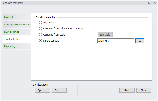
Figure: The Input Selection tab on the Generate Transects dialog
Options available include:
- All Conduits: New transects are generated for all conduits.
- Conduits from Selection on the Map: New transects are generated only for conduits selected on the Map.
- Conduits from Table: The conduits for which new transects are generated are specified in a table. Click on the Edit Table button to access the Select Conduits dialog.
- Single Conduit: Select the conduit for which a transect will be created from the ID Selector list accessed via the ellipsis button.
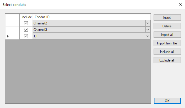
Figure: The Select Conduits dialog accessed via the Edit Table button
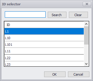
Figure: The ID Selector list
Running the Tool and Reporting
For options not involving manual digitization of transect lines on the Map, manually run the tool via the Run button at the bottom of the dialog.
A status report of the operation is displayed on the Reporting tab page of the dialog. The report may then be saved in a *.TXT file via the Save Report button. Use the Clear Report button to remove previous status reports displayed on the tab page ready for a new run of the tool.
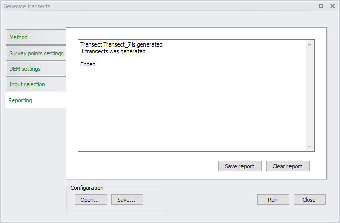
Figure: The Reporting tab on the Generate Transects dialog
Note
When a transect is created for a conduit, the conduit ID is indicated in the transect Description including the line coordinates for the transect.
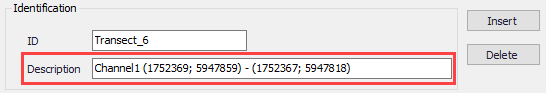
If another transect is made for the same conduit, the Description for the previous transect is removed to avoid confusion about which conduit a transect is associated.
Also, when extending transects, left and right bank locations are updated (if they are initially different than 0).
Configuration File
Save the tool setup configuration via the Save button located near the bottom of the tool dialog. An *.XML configuration file is created, which may be reused later via the Open button.