Pumps
Pumps are used to raise the hydraulic head of water. Pumps are represented as short links of negligible length. The simulation engine will automatically prevent flow reversal through a pump, and will issue warning messages when a pump operates outside of its normal operating range.
Pumps are either defined interactively on the graphical Map window using the Drawing tool (see figure below), or by manual data entry using the Pumps editor.
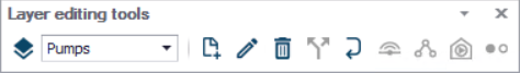
Figure: Pumps Drawing and Editing tools
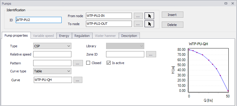
Figure: Pumps editor
The Pumps editor allows to define the pump´s ID, pump power curve, status, regulation, energy consumption, description, and other attributes.
Identification
Pump ID
This data entry is used to specify an ID to identify a pump link. The pump ID acts as a unique lookup key that identifies the pump link from all links.
From node, To node
These define the ID of the pump’s starting and ending nodes. Clicking  , an ID selection window pops up and allows selecting the ID from a list. Clicking
  , it allows the user to graphically select the node from the Map window and the connection of pipe will be changed simultaneously on the map.
Pumped flow is always assumed to move from the starting node to the ending node.
Pump Properties
This tab contains the pump operating characteristics.
Type
There are two options available to define the pump types:
- VSD: variable speed drive
- CSP: constant speed pump.
For VSD pump, user can control the relative speed of each pump by pressure or level control at node or by a flow control at a link. It can be set in “Variable Speed” Tab, which would only be activated for VSD pumps and would be grey otherwise.
Relative Speed
Relative Speed entry field allows the user to adjust the initial setting of the pump at the start of the simulation. For example, entering a value of 1.2 specifies that the pump operates at 1.2 times its normal speed at the start of the simulation.
Curve Type
There are four options available to define the pump specifications:
- Constant
- 1-point
- 3-point curve
- Table.
Constant is used when the pump characteristic curve is unknown and a constant power output is assumed. The data entry specifies the pump power rating, in hp or kw. The default power rating is zero.
1-Point type is used for a standard pump curve with no extended flow range, where the cutoff head is 133% of the design head and the maximum flow is twice the design flow.
3-Point type can be used to describe the flow-head relationship of the pump. The Shutoff Head is the head value at zero flow. The Design Head is the standard operating head, in units of ft. or m, and are by default zero. The Design Flow is corresponding flow rate, in the user-specified units, and by default zero. The High End Head is the head at the upper end of the normal operating flow range. The High End Flow is the corresponding flow rate. The Maximum Flow is the flow rate for the extended flow range. All heads are in units of ft. or m, and flows are in the user-specified units.
The Table type is used to define a Q-H Pump Curve, created by providing either a pair of head-flow points, or four or more such points. MIKE+ creates pump curves by connecting the points with straight line segments. The Q-H pump curve must be created in the ‘Curve and relations’ editor.
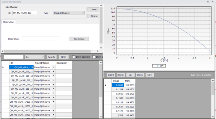
Figure: Curves and Relations settings
Is active
This check box allows the user to toggle the Active status of the pipe on and off. The simulations will omit all pumps that are not active.
Zone ID
This is an optional name for the zone to which the pump belongs. When a zone ID is specified, this zone will be listed in the 'Zones' editor. The '…' button can be used to select an existing zone.
QH plot
The plot shows the pump's QH curve, as defined from the above properties.
It can also display the simulated operating points from a result file. See Pump Q-H Plot chapter for more information.
Variable speed
MIKE+ is capable of modelling VSD pumps in extended period simulations.
Control type
Three types of control can be applied:
- Downstream node control: with this control type, the variable speed is a simplified setting for pressure control at the downstream nodes of the active pump
- Remote node control: with this control type, the variable speed is controlled by the pressure in any of the node in the network.
- Link control: with this control type, the variable speed is controlled by the flow in any link in the network.
Control item
In case of a node control, the control item can be either pressure or hydraulic gradeline. In case of a link control, the control item is flow.
Control node
The selected node where the pressure controls the variable speed, when the control type is 'Remote node control'.
Control link
The selected link where the flow controls the variable speed, when the control type is 'Link control'.
Control pressure
Users can type the pressure value in meter or psi in this box. This setting refers to the downstream node of the active pump to be controlled when the control type is 'Downstream node control', or the selected node when the control type is 'Remote node control'.
Control HGL
Users can type the hydraulic grade line value in this box. This setting refers to the downstream node of the active pump to be controlled when the control type is 'Downstream node control', or the selected node when the control type is 'Remote node control'.
Control flow
Users can type the flow value in this box. This setting refers to the control link of the active pump to be controlled when the control type is 'Link control".
Curve
The ID of the selected 'Pump pressure setpoint', ‘Pump HGL setpoint’, or ‘Pump flow setpoint’-curve, specifying the setpoint value as a function of time. The use of a curve is optional, and when no curve is selected the setpoint is constant. This option is only available when using the EPANET 2.2 version.
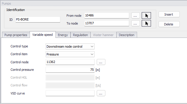
Figure: Variable Speed setting
Energy
MIKE+ is capable of modelling the cost of operating pumps. Within the Pump Energy tab, the user can define a method for cost calculation.
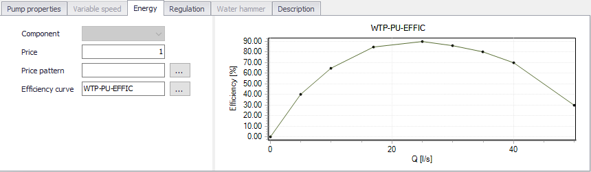
Figure: Energy settings
Price
The user defines an energy price (e.g. $/kw-hour) to be used. In this method, MIKE+ determines the energy consumed by the pump in kw-hours and multiplies the energy consumption by the price.
Leave blank if not applicable or if the global value supplied with the Parameters in Cost Analysis will be used.
Price pattern
The ID label of the time pattern used to describe the variation in energy price throughout the day. Each multiplier in the pattern is applied to the pump's Energy Price to determine a time-of-day pricing for the corresponding period.
Leave blank if not applicable or if the global pricing pattern specified in the project's Energy Options will be used.
Efficiency curve
The ID label of the curve that represents the pump's wire-to-water efficiency (in percent) as a function of flow rate. This information is used only to compute energy usage. Leave blank if not applicable or if the global pump efficiency supplied with the project's Energy Options will be used.
Regulation
Settings in this 'Regulation' tab suits CSP (Constant Speed Pumps). VSD pumps can be controlled from the 'Real-Time Control' editor. Please refer to the corresponding chapter for more information.
Control ID
This is the main ID of the control.
Description
This field allows users to type text to highlight the Control that is going to be set.
Settings
The settings contain three parts:
- Action
- Condition type
- Condition.
A radio button is used to set an Action. A pump can be set to Open, Close or a Value.
A radio button is used to set the Condition type, i.e. the type of condition that will trigger the action:
- If node below/above: This rule will execute the action if the pressure level in a specified node is above or below a specified level.
- At time: This rule will execute the action when the specified amount of time since simulation start has passed. When setting up a series of these rules there will be a time series of the setting in the right window.
- At clocktime: This rule will execute the action every day at the specified time.
The available Condition settings will depend on the selected condition type:
- When "If node below/above" is selected, the user must specify a node or tank ID in the first field and the threshold pressure level in the second field. Note that this is defined as the pressure at Elevation level for a node, and the pressure at Base elevation for a tank.
- When "At time" is selected, the user must specify a number and a time unit (hours/minutes) since start of simulation.
- When "At clocktime" is selected the user must specify a time of day in hours, minutes and AM/PM.
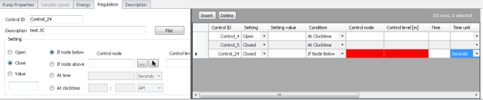
Figure: Control settings in Regulation tab
Description
This data entry allows to enter a description identifying the pump being entered. This description can be optionally displayed on the Map window and in reports generated by the Report Generator.
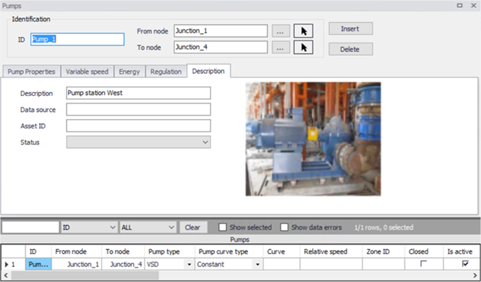
Figure: Layout of Description settings
Data Source
This data entry is used to specify a corresponding asset data source, which uniquely identifies the pump location (such as database table or a database file name) in the asset management system.
Status
This drop down selection list data entry allows you to define whether the pump is imported (i.e existing node was imported from the external data source), or is inserted, modified, GIS, calibrated or similar. By default, pump status is undefined.
Add Picture
The 'Add picture' button allows to add photo for individual pump. Once loaded from external source, the picture will be displayed on the right side.
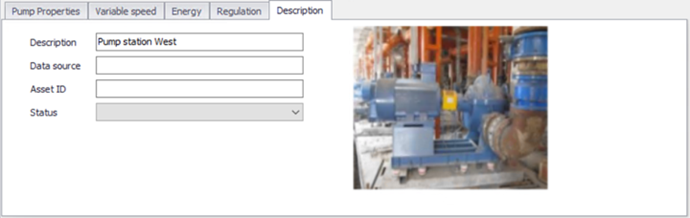
Figure: Pump picture displayed
Asset ID
This data entry is used to specify a corresponding asset pump ID, which uniquely identifies the junction node in the asset management system (such as GIS, for example).