Load Point
The allocation of geographically determined load points to the nodes and, or links of a collection system model is defined thtrough the Load Points section. The load points are geographical point features, typically representing a categorised wastewater load, such as domestic wastewater, commercial / industrial wastewater and infiltration.
It is possible to modify the additional categories to provide a tailored coding system to replicate the water loadings of the catchment.
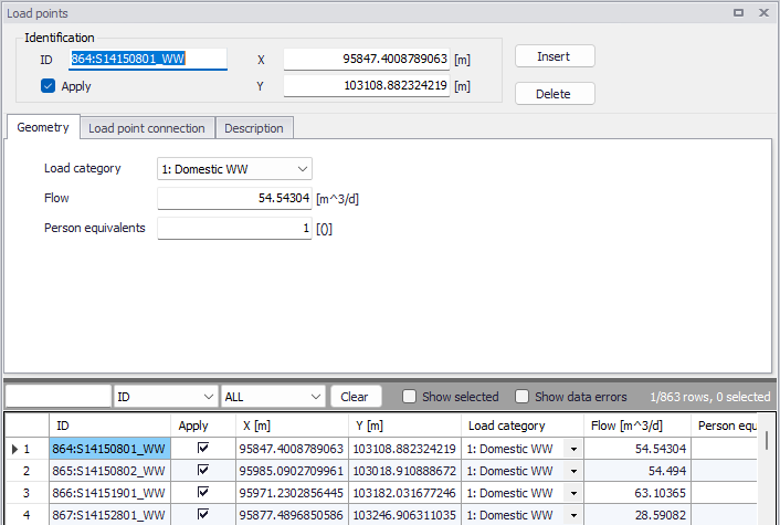
Figure: Load points grid
The 'Apply' check box allows the user to toggle the Active status of the load point on and off. The simulations will omit all load points that are not active.
There are three tabs within the ‘Load point’ editor: ‘Geometry’, ‘Load point connection’ and Description.
Geometry
Within the ‘Geometry’ tab, the load can be categorised and its flow and number of person equivalents can be specified.
The 'Load category' classifies the load point into one of the available load categories. Relevant when several categories of point loads are to be distinguished in the project.
The 'Flow' defines the load amount as volume per unit of time e.g. in m3/day.
When the load is associated to a 'Load point discharge' boundary condition, the boundary condition value is the flow value specified for the load. When the load is associated to a 'Load point discharge per PE' boundary condition, the boundary condition value is the flow value multiplied by the number of person equivalents specified for the load.
Load point connection
Load points can be connected to the model network through nodes and links, each load will be coupled to a single network element.
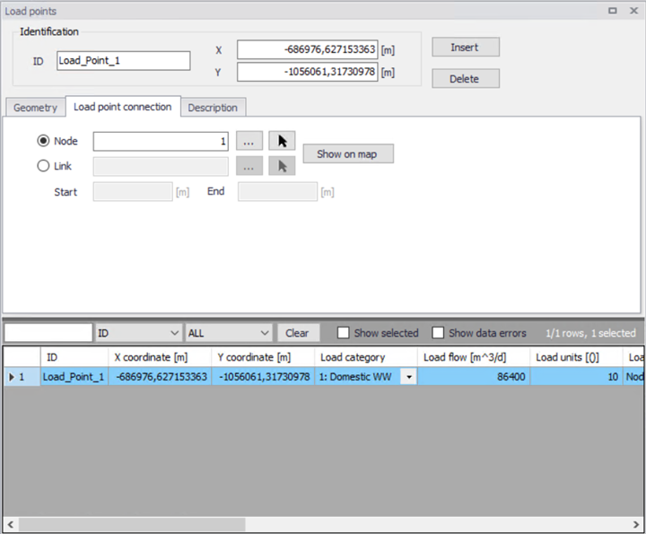
Figure: Load point connection
If using a link connection for the Load point, it is possible to defined the chainage start and end points.
The connections can be made via the asset ID Selector (using the '...' buttons) within the editor. Connections can also be defined on the map, using the "Connect load" graphical tool. This can be activated by clicking on CS network Connect tools Connect load, click on the desired load point in the map and then select a node to connect it to.
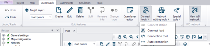
Figure: The Load Allocation toolbar
The work process for the geographical load allocation from the map is as follows:
-
Select the "Load points" layer from the target layer list, in the CS network toolbar.
-
Click on Connect tools | Connect load
-
Click on the desired load point in the map
-
Click on the desired node, and the connection will be automatically generated
MIKE+ plots the connection line between the load point and the selected node. If the current load point has already been allocated to some other node, the confirmation of the allocation action would re-connect the load to the current node.
This method is appropriate for individual corrections and/or for the smaller sets of load points.
Info
An automatic allocation of load points to collection system nodes can also be done using a GIS geocoding process. The geocoding process is initiated and controlled through the Connection tool.
Description
The description tab enables the modeller to record various load point information.
An 'Event ID' may also be associated with the load point. The purpose of the event ID is to automatically filter the load points to include in a given simulation by selecting the corresponding event ID during the simulation execution, i.e. in the 'Simulation setup' editor. When a load point is associated with a specific event ID, it will only be used in simulation setups defined with this same ID. The value 'Default (any event)' indicates that the load point is not associated with any specific event and will be used in all simulations. It is possible to either use the pre-existing IDs available in the list or to add or edit IDs using the '…' option at the bottom of the list. See the 'Simulation Setup' chapter for additional information.
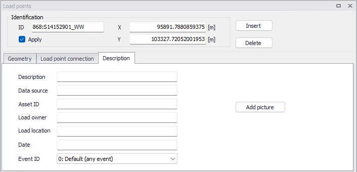
Figure: Load point description tab