Conduits
Conduits are pipes or channels that move water from one node (Junctions, Storage Units, Flow Dividers and Outfalls) to another in the drainage system. Their cross-sectional shapes can be selected from a variety of standard open and closed geometries. Irregular natural cross-section shapes are also supported.
The Conduits editor organizes the related input data into the following groups:
- Identification. General identification and connectivity information
- Geometry. Basic geometric information for the conduit
- Hydraulic Properties. Cross section data for specially-shaped conduits
- Hydraulic Loss. Head loss characteristics
- Miscellaneous. Other conduit properties
- Inlets. Specification of surface flow capture by inlets, for conduits modelling flow on the ground surface.
- Description. Optional descriptive information about the conduit. Also includes option for adding images of the structure.
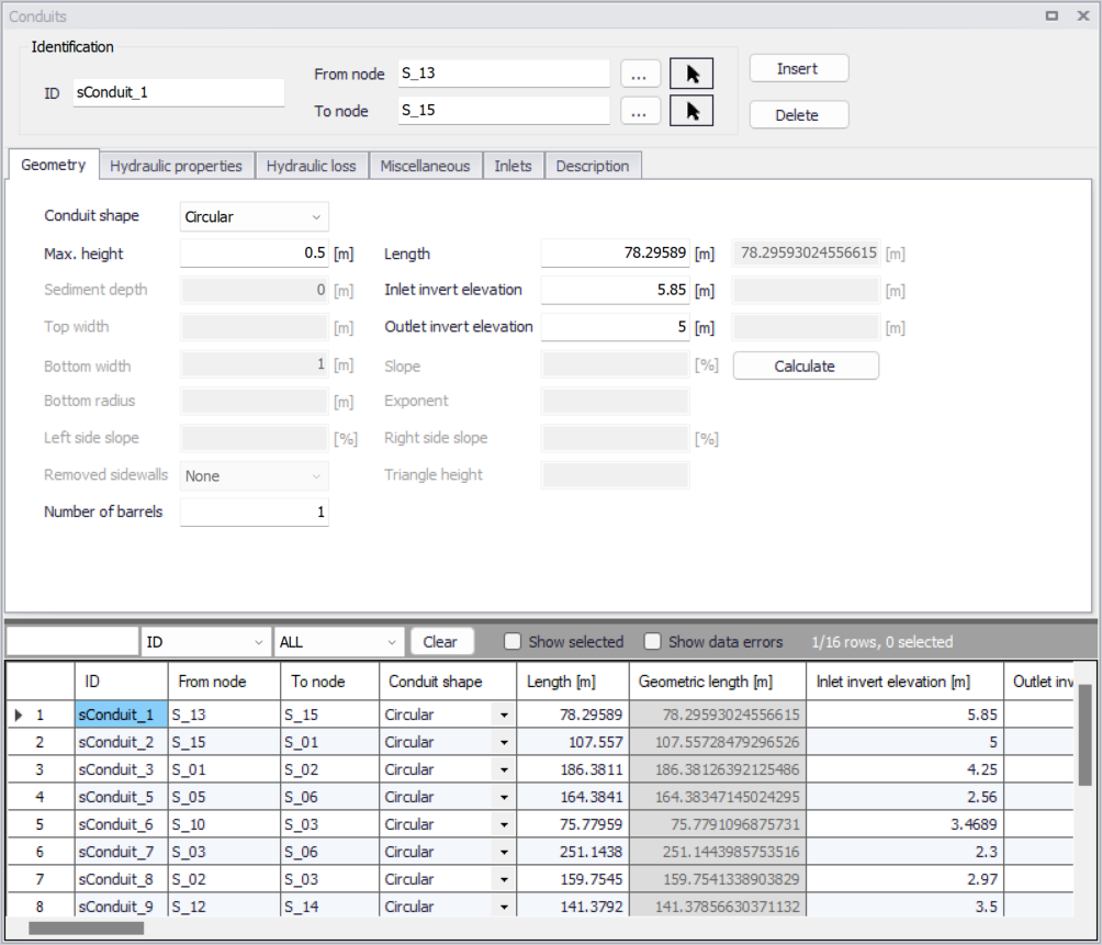
Figure: The SWMM network Conduits editor
Identification
Shows ID and connectivity information for conduits. Use the Insert and Delete buttons to add or remove items directly on the editor, respectively.
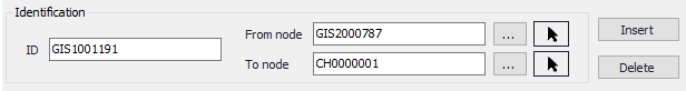
Figure: Conduits Identification group
| Edit field | Description | Used or required by simulations | Field name in datastructure |
|---|---|---|---|
| ID | Unique conduit Id | Yes | MUID |
| From Node | Upstream node | Yes | FromNodeID |
| To Node | Downstream node | Yes | ToNodeID |
| Description | |||
| Description | Descriptive information related to the structure | No | Description |
| Data Source | Reference to an external data source from which the record was imported | No | DataSource |
| Asset ID | Id in the asset management system | No | AssetName |
| Status | Status from a user- specified list in the Status Codes editor | No | Element_S |
| Network Type | Type of network i.e Stormwater, Combined or separate. The list of network types can be extended by the user. Network type can be specified for each element. | No | NetTypeNo |
| Tag | Optional label used to categorize or classify the conduit | No | Tag |
Table: Edit fields in the Conduits editor Identification group and Description tab (mss_Link)
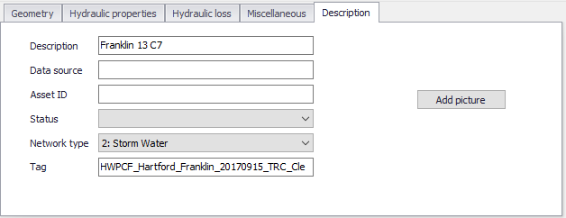
Figure: Conduits Description tab
Geometry
Specify basic conduit geometric information on the Geometry tab.
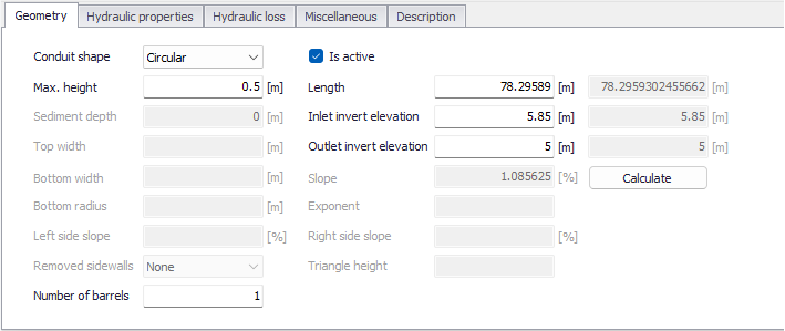
Figure: The Conduits editor Geometry tab
| Edit field | Description | Used or required by simulations | Field name in datastructure |
|---|---|---|---|
| Conduit Shape | Conduit cross section shape | Yes | ShapeTypeNo |
| Is Active | Option to include or disregard the conduit in model simulations | Yes | Enabled |
| Max. Height | Maximum conduit depth | Yes for all shapes except IRREGULAR shape | Depth |
| Length | Length of conduit | Yes | Length |
| Inlet Invert Elevation/Offset | Elevation or depth of upstream end of conduit above the upstream node invert | Yes | InletInvert |
| Outlet Invert Elevation/Offset | Depth or elevation of downstream end of conduit above the downstream node invert | Yes | OutletInvert |
| Sediment Depth | Sediment depth in conduit | Yes, if CIRCULAR shape | SedimentDepth |
| Top Width | Top width | Yes, if TRIANGULAR, PARABOLIC, POWER, RECT_TRIANGULAR, or RECT_ROUND shape | TopWidth |
| Bottom Width | Bottom width | Yes, if MODBASKETHANDLE shape | BottomWidth |
| Bottom Radius | Conduit bottom radius | Yes, if RECT_ROUND shape | BottomRadius |
| Left Side Slope | Left side slope of trapezoid | Yes, if TRAPEZOIDAL shape | LeftSideSlope |
| Right Side Slope | Right side slope of trapezoid | Yes if TRAPEZOIDAL shape | RightSideSlope |
| Removed side Walls | Option for defining walls along the cross section | If Shape = RECT_OPEN | SidewallsNo |
| Slope | Slope of the conduit, computed when pressing the ‘Calculate’ button | No | Slope |
| Exponent | Exponent in power function for describing the shape | Yes, if POWER | Exponent |
| Triangle Height | Height of triangular shape | Yes, if RECT_TRIANGULAR shape | TriangleHeight |
| Number of Barrels | A conduit can have a number of barrels, meaning that it consists of a multiple number of parallel pipes of equal size, slope and roughness. Default value is 1. | Yes | Barrels |
Table: Edit fields in the Conduits editor Geometry tab (mss_Link)
Info
A 'DUMMY' conduit shape is a connecting pipe without geometry.
Hydraulic Properties
Define cross sections for CUSTOM or IRREGULAR shape conduits on the Hydraulic Properties tab page.
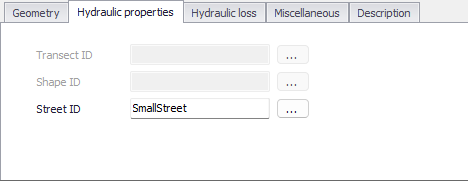
Figure: The Hydraulic Properties tab
| Edit field | Description | Used or required by simulations | Field name in datastructure |
|---|---|---|---|
| Transect ID | ID for the Transect describing conduit geometry expressed as station/elevation value pairs in the Transects editor | If Shape = IRREGULAR | TransectID |
| Shape ID | ID for the Shape describing conduit geometry expressed as depth/width values defined in the Curves and Relations editor | If Shape = CUSTOM | ShapeID |
| StreetID | ID for the Street shape describing conduit geometry, defined in the Streets editor | If Shape = STREET | StreetID |
Table: Edit fields in the Conduits editor Hydraulic Properties tab (mss_Link)
Hydraulic Loss
Define hydraulic loss parameters for conduits on the Hydraulic loss tab page of the Conduits editor.
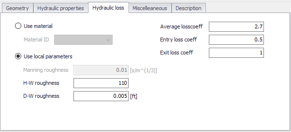
Figure: The SWMM Conduits Hydraulic Loss tab
| Edit field | Description | Used or required by simulations | Field name in datastructure |
|---|---|---|---|
| Use Material | Option to use loss parameters from the Materials editor | Yes | FricNo = 1 |
| Material ID | ID for the desired conduit material from the Materials editor | If FricNo = 1 | MaterialID |
| Use Local Parameters | Option to use loss parameters defined on the tab page | Yes | FricNo = 2 |
| Manning Roughness | Manning n value for the conduit | If FricNo = 1 and Conduit Shape \<> FORCE MAIN | Roughness |
| H-W Roughness | Hazen-Williams coefficient for the conduit | If FricNo = 1 and Force Main Equation = Hazen-Williams | ForceMainRoughnessHW |
| D-W Roughness | Darcy-Weisbach coefficient for the conduit | If FricNo = 1 and Force Main Equation = Darcy-Weisbach | ForceMainRoughnessDW |
| Average Loss Coeff | Average loss coefficient (using average velocity in conduit) | No | AvgLossCoeff |
| Entry Loss Coeff | Entry Loss coefficient (using entrance velocity) | No | EntryLossCoeff |
| Exit Loss Coeff | Exit loss coefficient (using exit velocity) | No | ExitLossCoeff |
Table: Edit fields in the Hydraulic Loss tab (mss_Link)
Minor losses are only computed for the Darcy-Weisbach Dynamic wave routing option. The minor losses, \(H_{L}\), are computed as:
(3.1) 
Where \(K\) is the energy loss coefficient, and \(v\) the flow velocity.
Miscellaneous
Define other parameters for the conduit on the Miscellaneous tab page.
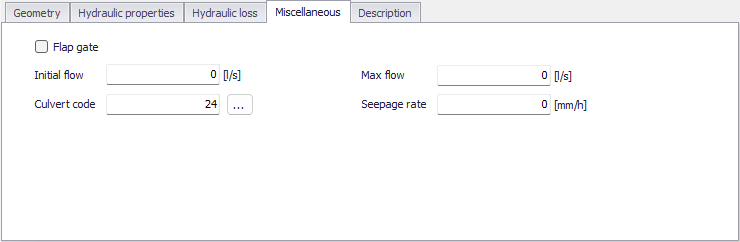
Figure: The SWMM Conduits Miscellaneous tab
| Edit field | Description | Used or required by simulations | Field name in datastructure |
|---|---|---|---|
| Flap Gate | Option for activating a flap gate preventing backwater flow | Yes | FlapGateNo |
| Initial Flow | Flow in conduit at start of simulation | Yes | InitialFlow |
| Max Flow | Maximum flow allowed through conduit | Yes | MaxFlow |
| Culvert Code | Culvert type code for inlet geometry if conduit is a culvert. Click the '...' button to open the list of code numbers with their descriptions. | No | CulvertCode |
| Seepage Rate | Seepage loss rate from the conduit | No | SeepageRate |
Table: Edit fields in the Miscellaneous tab (mss_Link)
Inlets
The 'Inlet's tab is used to apply an inlet structure into a conduit representing a street or a channel, and divert the flow captured by the inlet to another pipe's node.
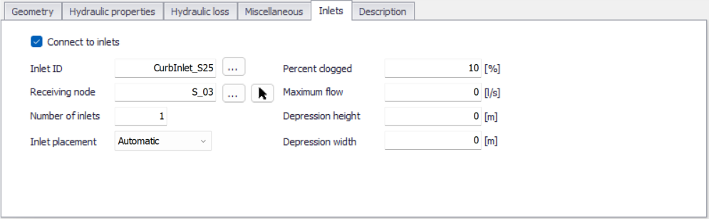
Figure: The Inlets tab from the SWMM Conduits editor
When flow from the street or channel conduit is captured by one or more inlets, the 'Connect to inlets' box must be ticked.
The following settings controlling the flow capture must then be specified:
- Inlet ID: the ID of the inlet structure to use, from the 'Inlets' editor. Use the '…' button to pick the inlet ID from the available list.
- Receiving node: the ID of the sewer node which receives the surface flow captured by the inlet. Use the '…' button to pick the node ID from the available list, or the arow button to pick the node from the map.
- Number of inlets: the number of identical inlets placed in the conduit. For two-sided street conduits, this number refers to pairs of inlets placed on each side of the street. For example, if two inlets are specified for a two-sided street, then a total of four inlets will be used, two on each side of the street.
- Inlet placement: specifies whether the inlet is placed in an on-grade or on-sag location. If the 'Automatic' option is chosen, SWMM will determine the placement based on the slopes of the conduits adjoining the inlet.
- Percent clogged: the percentage to which each inlet is clogged. The flow capture computed for the inlet is reduced by this percentage.
- Maximum flow: the maximum flow which can be captured by a single inlet. A value of 0 indicates that flow capture is unrestricted.
- Depression height: the height of any local gutter depression that exists over the length of the inlet. This local depression will be added onto any continuous depression that the conduit's Street section might have. A value of 0 indicates that no local depression applies. This parameter is ignored for drop inlets.
- Depression width: the width of any local gutter depression. It should be at least as large as the width that the inlet extends out into the gutter. This value is ignored if the depression height is 0 or if a drop inlet is used.
A connection line between the 'To node' of the conduit and the receiving node, representing the flow through the inlet, is shown on the map in the 'Inlets connections' layer.
Note
Grated, curb opening and slotted drain inlets can only be used by conduits with a Street shape. Drop grates and drop curb inlets can only be used by rectangular or trapezoidal channels. Custom inlets can be used in any conduit shape.