Bed Roughness
Bed roughness values for hydrodynamic computations may be defined for river networks in MIKE+.
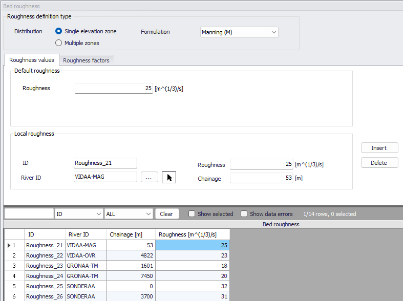
Figure: The Bed Roughness editor for river networks
Roughness Definition Type
Distribution
Two approaches may be applied for the bed roughness definition. Either a single (uniform) elevation zone or a so-called multiple zones approach.
With the 'Single elevation zone' option, bed roughness is applied using a uniform section approach. The bed roughness is defined by the selected roughness ‘Formulation’ and associated default (global) and local values if the 'Resistance type' has been set to 'Relative resistance' for the cross section. The resulting roughness number applied in the simulation is the defined bed roughness multiplied by the water level-dependent `Resistance factor' which is specified for the cross sections in the cross section editor (saved in the *.xns11 file).
With the 'Multiple zones' approach, the same rules apply, but it also offers a possibility for the user to divide the cross sections in a number of zones with different global/local bed roughness values. These zones would typically represent the various areas with a local bed roughness value (e.g. a zone without vegetation at the bottom of the cross section, a vegetation zone on banks, etc.) as illustrated in the figue below.
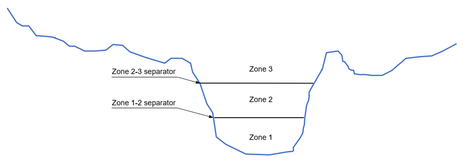
Figure: Multiple zones description of a cross-section
The resulting bed roughness numbers applied in the simulation are the zone values multiplied by the `Resistance factors' specified for the cross sections in the cross sections editor.
Zones separators, defining the threshold level or depth between two consecutive zones, must be specified in the 'Zones separators' tab.
During the simulation, the bed roughness applied to the cross section will vary in time as a function of the water level: at each time step, the bed roughness from the zone in which the water surface is, will apply uniformly to the whole cross section.
Formulation
Four bed roughness formulations are available from the Formulation dropdown menu:
- Manning (M) (Unit: m^1/3/s; Typical range: 10-100)
- Manning (n) (Reciprocal of Manning M; Typical range: 0.010-0.100)
- Chezy (C) (Unit: m^1/2/s)
- Darcy-Weisbach (k) (Unit: m)
For more information on the resistance formulas, please refer to the MIKE 1D Reference Manual.
The selected Formulation type will apply to both global and local roughness definitions, and no matter if the definition is based on a single zone or multiple zones.
Note
Bed roughness values are actually applied to processed data of the cross section. Each row from the processed data table gets the bed roughness value from the zone corresponding to the row's level. Interpolation will apply afterwards during the simulation, between the processed data levels.
Roughness values
Roughness numbers specified in this editor are a combination of a default roughness value and possibly one or more 'Local roughness' values.
The ‘Default roughness’ value represents a global bed roughness value. It is applied for all calculation points in the river network, unless local values are defined. For the 'Single elevation zone' approach, a uniform value needs to be specified. For the 'Multiple zones' approach, a default 'Number of zones' must be specified, which is applied to all calculation points of the river network unless local bed roughness values with a different number of zones is specified. The default bed roughness values for each of the default zones must also be specified.
Local roughness values are applied at specific locations defined by River ID and chainage. Add local roughness values through the editor using the ‘Insert’ button. Each local value is defined with:
- ID: Unique ID for the local roughness definition
- River ID: River branch ID
- Chainage: Location along the river branch for the local roughness definition
For the 'Single elevation zone' approach, a uniform roughness value for the location has to be specified in the 'Roughness' field. For the 'Multiple zones' approach, a local number of zones and their corresponding roughness values must be specified. The roughness values for the local zones are specified in the overview table at the bottom of the editor. This local number of zones can only apply if corresponding local zones separators also exist on the same reaches of rivers. Therefore, if a local bed roughness location is added, but if no local zone separators exist, the local bed roughness is defined with the global number of zones.
If two or more local values are defined on the same river, intermediate values are calculated by linear interpolation.
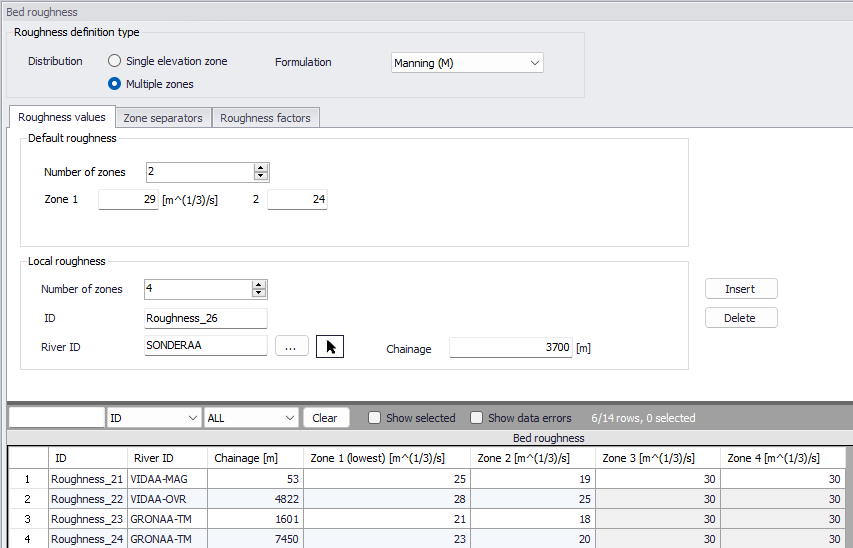
Figure: The Bed Roughness editor with the Multiple zones definition type
Zone separators
Zone separators define the vertical threshold elevation between two consecutive zones, when the 'Multiple zones' approach is applied.
The default zones separators are applied throughout all calculation points in the network, unless local zones separators have been defined. Zones separators' values may either be expressed as depths or levels. When expressed as depth, the specified depths represent the height from the bottom of the cross section up to the zone separators. Depths for the consecutive zone values must therefore increase.
Local zones separators must be specified at locations where a local number of zones is expected, or at locations where the zones need to have different elevations than the default values. Local zone separators are added using the 'Insert' button, and are located by a River ID and a chainage. For each location, the various thresholds between zones are specified in the overview table at the bottom of the editor.
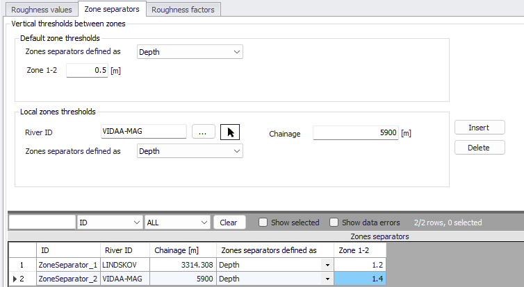
Figure: Definition of zone separators for the bed roughness definition with Multiple zones
Roughness factors
By activating the 'Apply bed roughness factors' option, it is possible to apply factors/coefficients to the bed roughness values, which can either be constant or varying in time. This facility e.g. allows to apply seasonal variations of bed roughness.
Applying a roughness factor higher than 1 will decrease the actual roughness of the river bed, whereas a value lower than 1 will increase the actual roughness. So, when the roughness type is Manning (M), then the Manning (M) value is multiplied by the factor. When the roughness type is Manning (n), then the Manning (n) value is divided by the factor. This applies regardless if the cross sections use a relative or Manning roughness value: if a cross section uses a Manning roughness value, then the roughness factor is applied to its processed data.
Roughness factors specified in this editor are a combination of a default (global) value and possibly one or more local factors.
The default roughness factor is applied throughout all calculation points in the river network, unless local values have been defined.
Local roughness factors are applied at specific locations defined by River ID, start chainage and end chainage.