Map Menu
The Map menu in MIKE+ provides tools and functionalities that can be used to modify and query model components on the Map.

Note
These tools are applicable only to the main Map (i.e. Map View) and not to result map plots
Navigate
The Navigate Toolbox contains tools allowing easy navigation around the Map.
Figure: The Navigation Toolbox on the Map menu ribbon
Zoom
Zoom in, zoom out, zoom next and zoom to previous options on the Map.
Zoom to selection
Zooms to the maximum extent of selected features on the Map.
Zoom full extent
Shows the full extent of model data.
Pan
When this tool is active, click and drag the map, to move it without changing the zoom level.
Pan selection
Centres the map to the selection without changing the zoom level.
Refresh
Ensures applied edits are reflected on the map.

Identify
The identify tool allows you to see the attributes of your data. Clicking the identify tool on a location will display the attributes of element at that location via the Properties and Result Explorer.

Clear highlighted
This clears any highlighted items (i.e. items highlighted when using the "identify" tool).
Go to coordinates
Opens a window to specify the X and Y coordinates at which the map should zoom.
Map bookmarks
You can switch from one bookmark to the other using map bookmarks, or you can save a specific model extent.
Scale
Input box displaying the map scale corresponding to the current zoom level on the Map. Specifying the map scale adjusts the zoom level accordingly.
![]()
Measure
Tool to measure distances on the map. The tool shows the total distance of the digitized polyline as well as the length of the last segment. It also shows a polygon's area, when digitizing a polyline and closing it by double-clicking the first point of the polyline.
Info
It is also possible to zoom to a specific item (pipe, pump, dike, etc.) by double-clicking on the corresponding item row in the editor. For example, to zoom to a pump, open the 'Pumps' editor, search for the pump of interest in the table, and double-click its row in the column containing the row number.
Selection
The Selection Toolbox offers various tools and functionalities related to the selection of model elements and features on the Map.
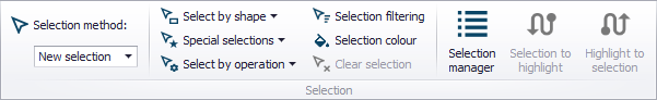
Figure: The Selection Toolbox on the Map menu ribbon
Selection method
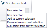
Choose how the selection shall be considered:
- New selection
- Add to current selection
- Remove from current selection
- Sub-select from current selection. Select from currently-selected elements.
Select by shape
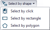
Options for how elements are selected on the Map:

- Select by click
- Select by rectangle
- Select by polygon: by drawing a free-form polygon on the Map.
Special selections
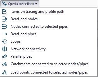
Options for selecting from elements categorized according to characteristics/properties:
- Items on tracing and profile path
(selects network items shown with the green path on the map, either obtained from connected flags or using the tracing forward / backward tool) - Dead-end nodes
- Pipes connected to selected nodes. In WD projects, this selects pipes connected to selected junctions, tanks and air-chambers.
- Nodes connected to selected pipes
- Dead-end pipes
- Loops
- Network connectivity
- Parallel pipes
- Catchments connected to selected nodes/links (CS and SWMM)
- Nodes/links connected to selected catchments (CS and SWMM)
- Load points connected to selected nodes/pipes (CS)
- Pump stations connected to selected pumps (WD)
- Demand allocation connected to selected nodes/links (WD)
- Network items coupled in selected 1D-2D couplings (2D overland)
- 1D-2D couplings of selected network items (2D overland)
- Network items for selected autocalibration controls (WD): selects network elements such as pipes and junctions, where parameters are calibrated or where targets are defined, in the Autocalibration special analysis.
- Network items for selected optimization controls (WD): selects network elements such as pipes and valves, where parameters are optimized or where targets are defined, in the Optimization special analysis.
Select by operation
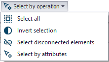
General operation options for making selections:
- Select all
- Invert selection: Switch selecting to previously unselected elements.
- Select disconnected elements: This tool changes the current selection on the map, to select all nodes and links that are disconnected from the current selection. Some network elements should be selected before performing this operation. All structures are considered being connecting elements. Inactive pipes ('Enabled' box being unselected) are considered being disconnecting elements.
- Select by attributes: Select elements from data tables using operations based on attribute values.
The 'Select by attributes' tool will select records from the layer (table) selected at the top of the tool, using the operation defined by the expression specified in the text field at the bottom. The operation must be expressed using the SQL syntax, e.g. text strings should be written between quotes (for example, LinkID = 'Pipe1'). The expression can be typed either manually or using the items and buttons available in the tool:
- The 'Fields' group provides a list of attributes existing in the layer being selected. Double-click an item from this list will insert the item name in the expression field.
- The 'Get unique values' button will list all values currently applied in the database for the selected 'Field' in the upper list. Double-click a unique value from the list will insert this value in the expression field. You can find a record from the list of unique values by typing its name in the 'Go to' field.
- The other buttons will insert operators in the expression field.
The 'Method' list allows selecting among four selection methods:
- New selection: This will clear any selection being active before executing the tool, and will then select new items using the specified selection expression.
- Add to current selection: This will keep any selection being active before executing the tool, and then append new selected items using the specified selection expression.
- Sub-select from current selection: This will keep only the records fulfilling the specified selection expression, from the selection being active before executing the tool.
- Remove from current selection: This will remove from the selection (being active before executing the tool) the records fulfilling the specified selection expression.
It is also possible to use fields / attributes from other tables than the one being selected, using the general SQL syntax, using the "from" command to search in other tables. For example, links from table msm_Link which have their upstream level (attribute msm_Link.UpLevel) lower than the invert level of their upstream node (msm_Node.InvertLevel for the node selected in msm_Link.FromNodeID), can be selected using the following SQL expression:
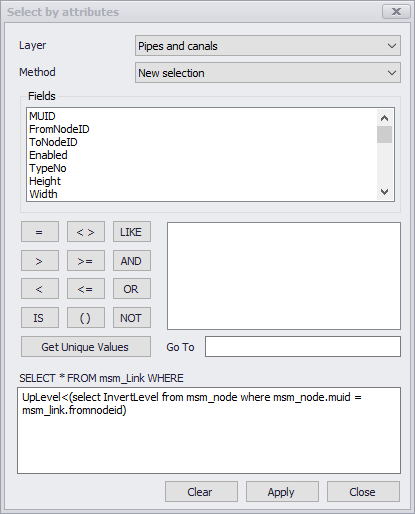
Figure: Selecting links from the 'Pipes and canals' layer, having their upstream level lower than the invert level of their upstream node
It is also possible to create a selection depending on another selection. To achieve this, the other selection must be saved to the database using the 'Selection manager'. For example, gates structures located on rivers selected in the selection called 'RiverSelection', can be selected using the following SQL expression:
RiverID = (select itemmuid from m_Selection where m_Selection.selectionid = 'RiverSelection' AND m_Selection.tablename = 'mrm_Branch')
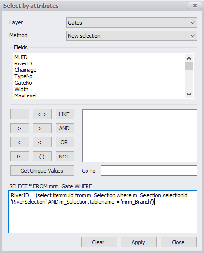
Figure: Selecting gates located on rivers selected in the selection called 'RiverSelection'
It is also possible to select some records based on the value of an attribute status (see Flagging. For example, nodes from table msm_Node with the status of the 'Diameter' attribute set to 'Verified' can be selected using the following SQL expression:
muid IN (select ItemMUID from m_Status where m_Status.TableName = 'msm_Node' AND m_Status.FieldName = 'Diameter' AND m_Status.StatusText = 'Verified')
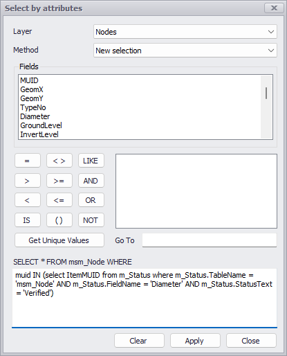
Figure: Selecting nodes with diameter’s status set to 'Verified'

Selection colour
Option for defining colour to use on the Map to highlight selections.

Clear selection
Deselect all selected elements.

Selection filtering
Option for defining model elements from where selections can be made.
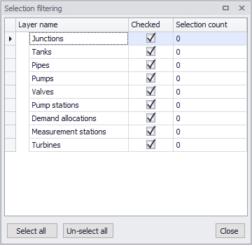
Figure: Selection filtering dialog for WD models

Selection manager
Dialog wherein user-defined selection lists may be specified for easy reuse in multiple functions and tools for the project and in the application.
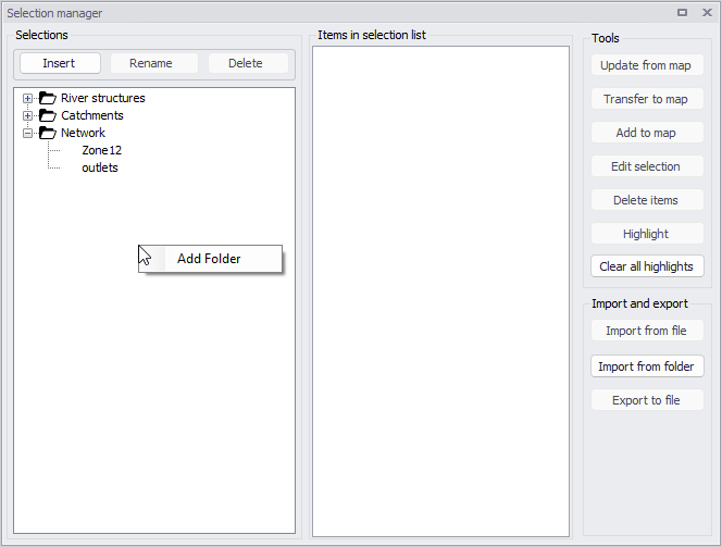
Figure: The Selection Manager in MIKE+
The dialog contains the following sections:
- Selections: this is the main list containing user-defined selections. Selections are inserted / deleted / renamed using the buttons above the list.
- Items in selection list: this is the content of the selection which is selected in the 'Selections' section, showing typically model features, boundary conditions, etc. This content is typically updated using the buttons in the 'Tools' section.
- Tools: the following buttons are used to edit the content of the selection.
- Update from map: this action updates the current selection list, so that the list contains all items currently selected on the map and in the various editors. It is typically used after creating a new selection list, to save the current selection on the map.
- Transfer to map: this action selects on the map and in the editors, all items included in the selected list. Items previously selected get unselected, if they are not part of the list.
- Add to map: this action adds to the selection on the map and in the editors, all items included in the selected list. Items previously selected remain selected, even if they are not part of the list.
- Edit selection: this action opens a window showing the full lists of items from the various database tables, to manually add or remove items from the selection.
- Delete items: this action removes the selected items from the selection. It does not delete them from the project.
- Highlight: this action highlights on the map all items included in the selected list.
- Clear all highlights: this action clears all highlights from the map.
- Import and export: the following buttons are used to save or load the selection to external files.
- Import from file: this action loads the content of the selection from a .mus text file.
- Import from folder: this action loads the content from multiple .mus files located in the selected folder.
- Export to file: this action exports the content of the selection to a .mus text file.

Selection to highlight
To highlight (i.e. in pink) selected elements on the Map. Elements are only subject to querying and not editing when highlighted (as opposed to selected).
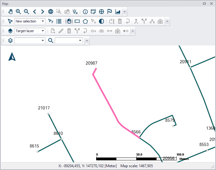
Figure: Pipe element highlighted on the Map

Highlight to selection
Highlighted elements (i.e. in pink) on the Map are selected. Elements are highlighted when e.g. the Identify tool is used to view its properties from the Map.
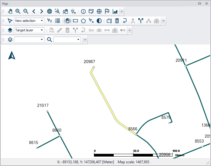
Figure: Pipe element selected from the Map
Profile and Tracing
The Profile and Tracing Toolbox contains tools for creating longitudinal profiles along model networks from the main Map. It also has tools for tracing and checking network connectivities.

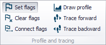
Set flags
Tool for placing flags at node locations on the main Map view in preparation for creating longitudinal profile plots or analyzing network connectivity.
Clear flags
Removes all flags set on the main Map.
Connect flags
Identifies connections between the first and last set flags along the model network on the Map.

Draw profile
Window presenting generated longitudinal profile plots. Also used for creating new profile plots when flags are moved/re-set on the Map.

Tracing forward
Tool for tracing forward connections from a set flag point on the Map.
When no result layer is available on the main map, the tracing is based on the From and To Node definitions of link elements. The forward direction of a link is from its 'From' node to its 'To' node.
When a result layer is available on the main map, the 'Select target to trace' window will appear, offering two tracing methods:
- From model network connectivity: the tracing is based on the From and To Node definitions of link elements
- From flow direction results: this will use the actual flow direction computed during the simulation. For this option, it is therefore required to select the result file and the corresponding date and time of the results to be used. It is also required to specify a threshold: the tool won't trace results in links where the resulting value is smaller than the specified threshold.
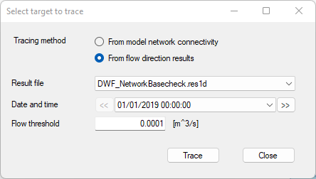
Figure: The dialog controlling the tracing settings
When tracing with results, the flow analysis is performed using the average flow on the link, and the link is either entirely included or entirely excluded from the tracing path. The flow tracing will therefore not stop at an intermediate grid point along the link where the discharge result will become smaller than the threshold.
Forward tracing is also available from extra result maps, by selecting 'Forward tracing' in the context menu on the map, after setting a flag on this result map.
Tracing backward
Tool for tracing connections backwards from a set flag point on the main Map.
The logic is the same as for the forward tracing, but tracing in the opposite direction. When tracing using the network connectivity, the backward direction of a link is from its 'To' node to its 'From' node.
Backward tracing is also available from extra result maps, by selecting 'Backward tracing' in the context menu on the map, after setting a flag on this result map.
Also see chapter Profile Plots for related information.
Context menu
When the 'Set flags' button is active in the ribbon, right-clicking on the map opens the context menu shown on the figure below, which offers extra options to work with flags.
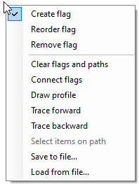
Figure: The context menu options to work with flags
This menu offers shortcuts for the actions also available in the ribbon (Draw profile, Trace forward, etc.) as well as options to edit flags (reorder or delete them). It is also possible to save the list and location of the current flags to a file (*.path), which allows reusing the same path at a later stage by loading the flags again from the file.
Map View

Background map
MIKE+ provides several background map options, available either as online resources as shown in the figure below or installed on the local computer. The choice made during project creation can be modified at any time. Use the Background Map tool from the Map menu ribbon, or launch the Background Map editor from the Setup tree view. Select a background map from the available options as shown in the figure below.
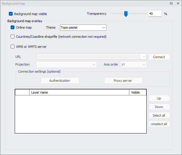
Figure: MIKE+ background map options

Add layer
Activate this tool to add data layers to visualize on the Map or use in the model via the Add Layer dialog. Added layers appear in the Layers and Symbols panel tree view.
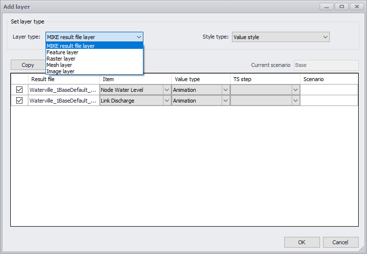
Figure: Add Layer dialog
Show compass
Show the compass symbol on the map.
Show scale bar
Show the map scale bar on the map.
![]()
Export map
Activate this tool to save the map view to an image file. The tool allows selecting the file type as well as the resolution (number of pixels) of the created file, which can be used to coarsen the picture to reduce the image size.
When active, the option to save the image coordinates to a world file will also create an extra text file holding the coordinates of the image. This file can later be detected and used by MIKE+ or other software products to display the image at the proper location on a map.
Snapping
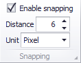
Specifies the snapping tolerance used between features when doing graphical editing. The units can be selected from the options of either pixel or meter.