Valves
A valve is a functional relation which connects two nodes of a MIKE 1D urban network.
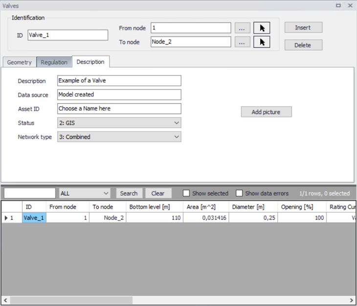
Figure: Valve dialog
In the real world a valve may be located in a manhole or a similar construction which you normally would define as a node in the model configuration. The numerical solutions for the flow equations, however, need a model configuration with two nodes where the valve is defined as the connection between the nodes. The valve will then be placed between the two nodes as the flow connection.
It is possible to define several valves between the same two nodes if this is required. This is similar to the possibility of having more than one pipe as the link between nodes. The generation of the computational grid shown in model configuration of orifice is also applied for pumps, weirs and valves. The numerical solution of the flow equations will depend on the selected device. Please refer to the MIKE 1D Reference Manual for more details about this.
It is recommended not to place the two nodes in the same spot, instead place the nodes a short distance apart. The reason is that the node head loss computation will have a component from change of flow direction. If the two nodes surrounding the device are placed exactly at the same location then the computational engine cannot determine the direction of the flow from the coordinates of the nodes and a default direction will be applied. This may unintentionally introduce a change in direction and therefore also an unexpected head loss.
By using a small displacement of the nodes the change in flow direction will be determined based on the coordinates and angles between the connected pipes. Therefore consider carefully the placement of the nodes with respect to the actual construction.
A valve is specified by a diameter, flow area (by default calculated on the basis of the diameter, but it is possible to overwrite this value) and an invert level.
It is possible to specify a valve to be a non-return valve and thereby preventing flow in the negative flow direction. A rating curve is specified to define the relation between the valve opening (%) and resistance (k). The rating curve is specified under “Tables| Curves & Relations”.
The valve is by default static, in which case the valve opening must be specified. It is also possible to define a valve to be regulated by control rules and then the valve opening may be controlled during the simulation using control rules.
| Edit field | Description | Used or required by simulations | Field name in data structure |
|---|---|---|---|
| Description | User’s descriptive information related to the valve | No | Description |
| Data source | Reference to an external data source (table ID) where the record has been imported from | No | DataSource |
| Asset ID | Reference to an ID used in external data sources | No | AssetName |
| Status | Data status for the entire record, serves for keeping track on the source of information | No | Elements |
| Network Type | Attributes the valve to a certain type of network. Used in case where two or more different networks are included in the same project | No | NetTypeNo |
| Valve ID | A unique name for the valve. Up to 40 characters (letters, numbers, blank spaces and underscore characters) | Yes | MUID |
| From node | ID of Node where valve is located | Yes | FromNodeID |
| To node | ID of Node where valve is discharging to | Yes | ToNodeID |
| Apply | This check box allows to toggle the Active status of the valve on and off. The simulations will omit all valves that are not active. | Yes | Enabled |
Table: Identification and connectivity edit fields of the MIKE+ valve editor (Table msm_Valve)
| Edit field | Description | Used or required by simulations | Field name in data structure |
|---|---|---|---|
| Diameter | The default value of the area (the field “Flow Area”) is calculated on the assumption of a circular valve, with the diameter specified in this field. Furthermore, the transition to a pressurized valve is defined by the invert level plus the diameter. | Yes | Diameter |
| Invert Level | The invert level defines the minimum water level, which generates flow through the valve | yes | InvertLevel |
| Flow Area | A user specified flow area overwrites the default valve area computed on the basis of a circular cross section. | Yes | Area |
| Valve Opening | Defines the opening of the valve in percentages (value between 0 and 100). When applying control rules, this value is not applied, and the opening value is controlled by the control rules | Yes | Opening |
| Rating Curve | Reference to the tabulated k-opening function | Yes | RatingCurveID |
| Non return flap | Indicating a flap-gate built-in valve (i.e. no return flow possible) | Yes | FlapNo |
| Controlled by control rules | If selected, the valve is controlled using control rules, as defined in the 'Control rules' editor. Control rules will apply only when both this check box and the 'Apply' check box in the control rule definition are ticked. Note that the regulation with control rules is always disabled, when the 'Control rules' module is unselected in the 'Model type' editor. | Yes | ControlTypeNo |
| Max opening | Maximum opening condition of the valve when controlled by control rules | Yes, if control rules apply | |
| Min opening | Minimum opening condition of the valve when controlled by control rules | Yes, if control rules apply | |
| Max speed | The maximum velocity for movement of the flap | Yes, if control rules apply |
Table: Geometrical and hydraulic properties, edit fields of the MIKE+ valve editor (Table msm_Valve)