Control Rules
Define controllable devices and the respective control settings on the Control rules editor.
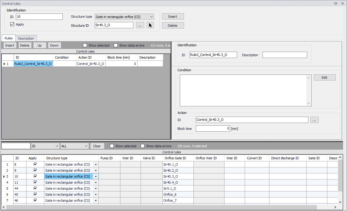
Figure: The Control rules editor
The operational control rules for controllable devices are specified in this editor. The control is specified as a set of rules linking logical conditions and control actions. The rules are evaluated sequentially following the rules list sequence.
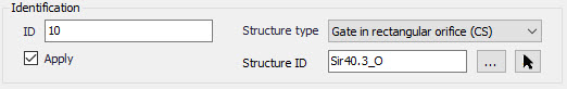
Identification
Specify the ID of the control rule in the Identification group box.
Use the ‘Insert’ button to add a new control rule configuration in the project.
Define the type of controlled device for which to apply the control rule configuration in 'Structure type' list. The types 'Gate in rectangular orifice' and 'Weir in rectangular orifice' apply to orifices on the collection system network. Therefore, a 'Weir in rectangular orifice' type will control an orifice, and not an ordinary weir.
The difference between a ‘Gate in rectangular orifice’ and ‘Weir in rectangular orifice’ is that the gate blade edge moves downwards from the top of the orifice (to the bottom), while the weir blade edge moves upwards from the bottom of the orifice.
When the device 'Type' has been selected, the controlled structure ID must be specified
The 'Apply' option controls whether the active control rules configuration is active during the simulation or not.
Rules
The various rules applying to the current structure are specified in the Rules tab.
Add and remove rules using the Insert and Delete buttons above the secondary table on the left.
For each rule, an ID and a description may be supplied in the Identification group, and an action must be selected.
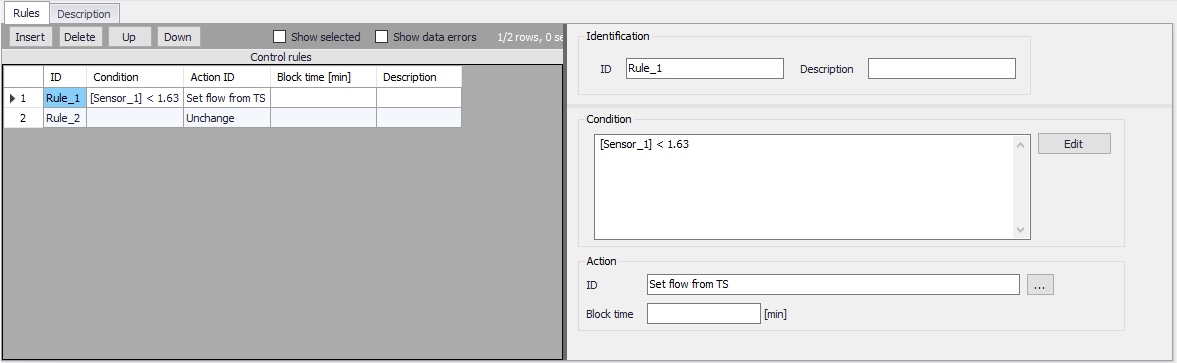
Figure: Selection of conditions and actions defining the rules
Any number of rules can be specified to control the device. When multiple rules apply, the rules are sequentially evaluated starting from the top, at every time step of the simulation. This means that appropriate sequence of rules is essential for the achievement of the desired control logic.
Use the 'Up' and 'Down' buttons above the secondary grid to modify the order of the Rules. When multiple rules are included, they must be associated to a 'Condition', controlling when a rule applies.
Evaluation of a logical condition belonging to a rule as 'TRUE', leads to the selection of the associated action. If a logical condition is 'FALSE', the evaluation proceeds to the next rule on the list.
If no logical condition is specified, the rule is unconditionally evaluated as 'TRUE'. This implies that the last rule in the sequence must not include any logical conditions in order to ensure a selection of a 'Default' control action if all previous specified conditions are found 'FALSE'.
Condition
A logical condition demarcates the boundaries of a certain operational situation in the controlled system. This frame consists of an arbitrary number of independent logical tests on the various operational variables, where the relation of the actual value (or state) of the variable (provided by a sensor) is tested against the specified threshold (limit) value (or state). The individual tests are evaluated as TRUE or FALSE, with the outcome depending on the actual variable value (or state), the threshold and the specified operator.
A condition is specified as a mathematical expression in the Condition input box is the editor.
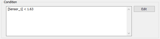
Figure: The Condition input box in the Rules tab
The implementation of mathematical expressions in MIKE+ is very general, supporting a comprehensive set of mathematical functions and operators. Click on the Edit button to the right of the Condition input box to launch the Expression editor.
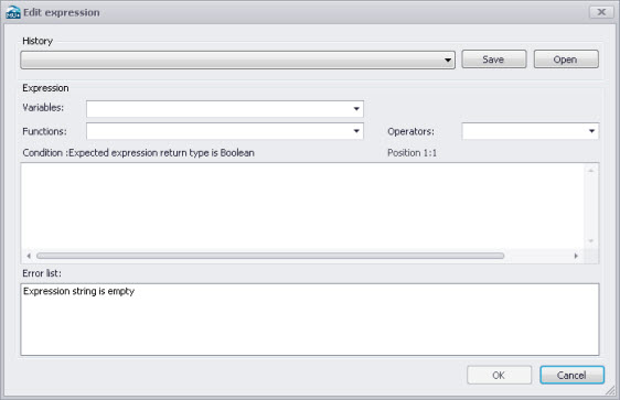
Figure: The Expression editor
Mathematical expressions are formulas or expressions trees. The formulas support the standard mathematical functions like sine, cosine, abs, power etc. On top of these standard mathematical functions, a number of specific MIKE 1D engine control functions are available.
Note on output type
A Boolean data type (i.e. TRUE, FALSE) is expected from the evaluation of the expression for Conditions.
Note about syntax
The condition must be written with the syntax from C# programming language. Therefore, the few rules below should apply:
- An equality check is written ==. For example, the condition for verifying if the simulation time is in August is: Month(SimulationTime()) == 8
- The AND condition is written &&, whereas OR is written ||. This is shown in the 'Operators' drop-down list, but the text AND and OR should not be used in the condition.
- A path to file must be written with double \ For example, if a condition looks up the time series C:\Data\TS.dfs0, the file path in the function must be written C:\\Data\\TS.dfs0.
- The decimal separator must always be a point.
Action ID
The corresponding Action for a given Condition. Options are taken from the Actions editor. The choice of the controllable device determines relevant control actions.
Block Time
The Block Time ensures that a certain rule is applied for a minimum period. This means that the system is locked to a certain rule in a period equal to the block time after it is activated, even if the condition is no longer TRUE.
Some notes when specifying rules are:
- All control actions used to control a specific device must be of the same function type - corresponding to the specified device Type and Control Type.
- For PID control, all control actions must refer to the same setpoint sensor (i.e. Input). Changing the setpoint sensor during simulation is not allowed.
PID Settings
When starting a simulation, the system checks if these conditions are fulfilled and in the case of any violation, the simulation will not start.
Description
One may include a description of the control rules configuration in the Description tab of the editor. An image file (e.g. of the controlled device) may also be added using the 'Add picture' button.
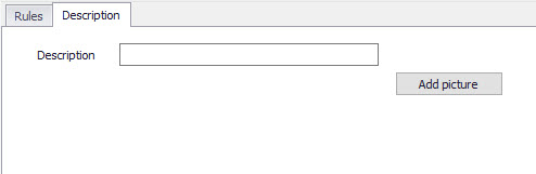
Figure: The Description tab in the Control rules editor
Difference between weir and weir in orifice
It is possible to define weirs in two different ways. One way is through the 'Weir' dialog, either on a collection system or on a river network, which we will refer to as an 'ordinary weir'. The second way is to use the combination of an orifice and the controllable device type 'Weir in rectangular orifice'.
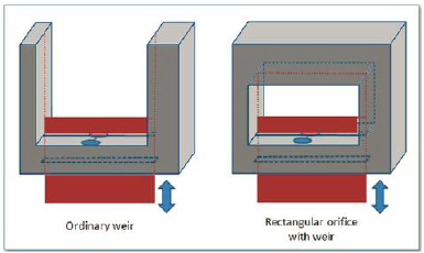
Figure: Difference between ordinary weir and a weir in rectangular orifice
The main difference is that the 'Weir in rectangular orifice' can close the orifice completely while the ordinary weir is always open upwards. It has no ceiling and in principle the flow can always pass over the weir if the water level is higher than the weir crest level.
For the 'Weir in rectangular orifice', once the weir fully closes the orifice then no flow will pass the weir even if the water level is above the crest level.