Outlets
Outlets are flow control structures typically used to control outflows from storage units. They are used to model special flow-head relations that cannot be characterized by either orifices or weirs. MIKE+ SWMM represents an Outlet as a link connecting two nodes, where the outlet itself is placed at the upstream node.
Outlets attached to storage units are active under all types of flow routing. Those attached to other types of nodes are active only under Dynamic Wave flow routing; otherwise the flow through them is zero.
The Outlet editor organizes the related input data into the following groups:
- Identification. General identification and connectivity information
- Hydraulic Properties. Hydraulic and geometric parameters for the outlet
- Description. Optional descriptive information about the element. Also includes an option for adding images of the structure.
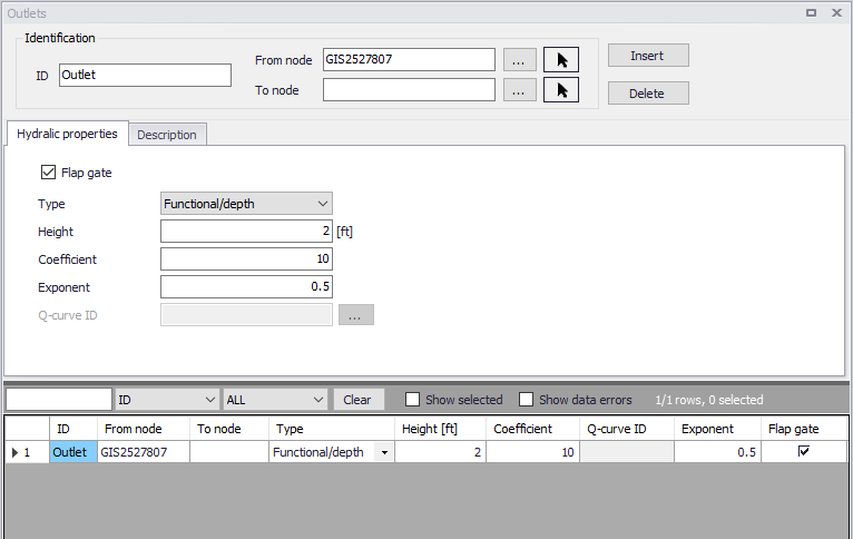
Figure: The SWMM Outlets editor
Identification
The identification group box holds element ID and connectivity information. Use the Insert or Delete buttons to add or remove records from the editor, respectively.
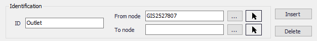
Figure: Outlets Identification groupbox
| Edit field | Description | Used or required by simulations | Field name in datastructure |
|---|---|---|---|
| ID | Id of the Outlet | Yes | MUID |
| Location | Node location of the outlet | Yes | FromNodeID |
| To | Receiving node | No | ToNodeID |
| Description | |||
| Description | Descriptive information for the outlet | No | Description |
| Data Source | Reference to an external data source from which the record was imported | No | DataSource |
| Asset ID | Id in the asset database | No | AssetName |
| Status | Status according to user specified list in Status Codes editor | No | Element_S |
| Network Type | Network type describes the type of network i.e Stormwater, Combined or separate. The list of network types can be extended by user. Network type can be specified for each hydraulic element. | No | NetTypeNo |
| Tag | Optional label used to categorize or classify the outlet | No | Tag |
Table: Edit fields in the Outlets Identification groupbox and Description tab (mss_Outlet)
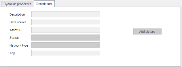
Figure: Outlets Description tab
Hydraulic Properties
Specify geometric and hydraulic parameters for outlets on the Geometry tab.
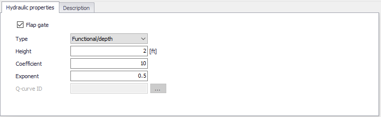
Figure: Outlets editor Hydraulic Properties tab
| Edit field | Description | Used or required by simulations | Field name in datastructure |
|---|---|---|---|
| Flap Gate | Option for adding a flap gate preventing backflows | Yes | FlapGateNo |
| Type | Outlet Type: Tabular/depth, Tabular/head, Functional/depth, Functional/head | Yes | TypeNo |
| Height | Minimum water depth at upstream node for outflow to occur | Yes | Height |
| Coefficient | Coefficient of power function that relates outflow to head across the outlet for a Functional outlet | Yes, if Outlet Type is Functional | Qcoeff |
| Exponent | Exponent of power function that relates outflow to head across the outlet fir a Functional outlet | Yes, if Outlet Type is Functional | Qexpon |
| Q-curve ID | ID of rating curve with outflow rate as a function of head across the outlet for a tabular outlet | Yes if Outlet Type is Tabular | QcurveID |
Table: Edit fields in the Outlets Hydraulic Properties tab (mss_Outlet)
Outlet types are based on how flow is computed as a function of freeboard depth or head across the outlet:
- Tabular/depth. Uses a tabulated curve of flow-freeboard depth values.
- Tabular/head. Uses a tabulated curve of flow-head difference values.
- Functional/depth. Uses a power function \(Q = \text{Coefficient} \cdot y^{\text{Exponent}}\) where \(y\) is the freeboard depth above the outlet's opening.
- Functional/head. Uses a power function \(Q = \text{Coefficient} \cdot y^{\text{Exponent}}\) where \(y\) is the head difference across the outlet.
An outlet can have a flap gate which restricts flow to only one direction and prevents backwater flow.
The flow through an outlet is determined by a user-supplied function or table of flow versus head difference across the outlet (Q-curve ID). This flow can be controlled dynamically through user-defined control rules.