Introduction to Stormwater Quality (SWQ)
SWQ - A model associated with urban catchments and rainfall-runoff modelling
The importance of wide-ranging and yet efficient modelling of stormwater quality on urban catchments and the transport of polluted stormwater in the urban drainage networks is growing with increased focus on local handling of stormwater, drainage network separation, stormwater treatment prior to release to recipients, as well as untreated stormwater overflows.
Stormwater pollution associated with urban catchment surfaces includes dissolved matter and suspended particles originating from:
- Soil erosion
- Erosion of construction materials (roofs, roads)
- Air borne pollution (e.g. industrial emissions particles)
- Local biological pollution related to humans and wildlife (various waste, birds droppings)
- Traffic debris
- Etc.
MIKE+ SWQ simulates stormwater quality as a special model associated with urban catchments and stormwater runoff and infiltration. This is illustrated in the figure below.
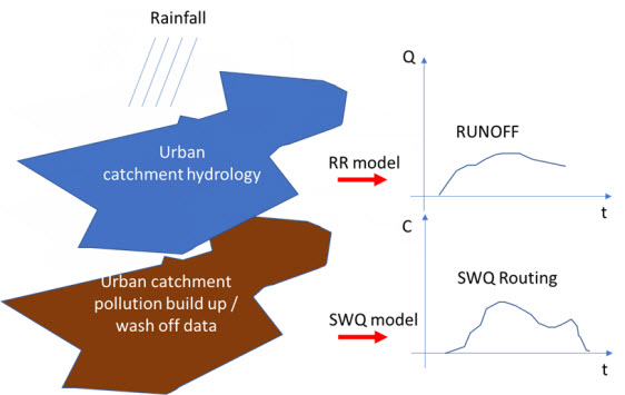
Figure: Rainfall-runoff and SWQ models act simultaneously on an urban catchment. Both models are driven by the rainfall and by the model parameters controlling the quantities and dynamics of runoff and surface pollution, respectively, being routed towards the catchment outlet.
Spatial and temporal variation of pollution in urban catchments
Model catchments vs. spatial distribution of surface pollution
The amount of surface pollution on urban catchments varies both in space and time, governed by types of pollutants, types of catchment surface and its uses. This variation needs to be captured as correctly as possible in the simulation model in order to achieve realistic model results.
The urban drainage model area is typically delineated into a number of sub-catchments, with delineation determined by the drainage network layout, topography or even administrative limits (parcels, urban districts, etc.).
Sometimes, the sub-catchment delineation is done by a simple division (e.g. Thiessen polygons), i.e. is based on purely geometrical reasoning. Only in rare cases, such delineations are appropriate for efficient characterisation of surface pollution loads generated on such sub-catchments.
Therefore, model sub-catchments would typically include different surfaces, such as building roofs made of different material, roads with various traffic intensity and with different paving, green areas with different vegetation, etc.).
Each of these surfaces may have different usage as well. This means that a single model catchment may be a source of various pollutants, differing by:
- Pollutant type:
- Organic pollution
- Chemicals
- Microplastic
- Heavy metals
- Etc.
- Pollutant origin and build-up/wash-off mechanism:
- Airborne (wind, smog)
- Area use (traffic, people, animals, local industry)
- Erosion of surface materials (metal roofs, asbestos, PAH…)
- Soil erosion
- Attachment to surface sediments:
- Particulate suspended, attached to surface sediments
- Particulate suspended, on its own
- Dissolved
These differences get manifested in various pollutants' quantities and their different behaviour on the catchment surface in dry weather (build-up) and when exposed to rainfall (wash-off). The following simple examples illustrates a typical situation.
A catchment has a total area of 2.1 ha. From the point of view of surface pollution, three types of surfaces may be distinguished: building roofs (15% or 0.315 ha), roads (10% or 0.21 ha) and the remaining 75% (or 1.575 ha) is green area. Each of these surfaces may be a source of various pollutants by itself and is exposed to build-up of exogenous pollution by different intensity and dynamics, depending on the surface exposure to external impacts. Further, these pollutants may behave differently in terms of wash-off by action of rainfall.
A MIKE+ model may contain many - often thousands - of such catchments.
Decomposing catchments to pollution-related layers
In order to capture such situation correctly and efficiently in the model, the catchment (i.e. each sub-catchment in the model) is decomposed to a number of stacked, geographically identical catchments. In the described case, the catchment is represented by three layers, each one representing one of the three surface types. This is illustrated in the following figure:
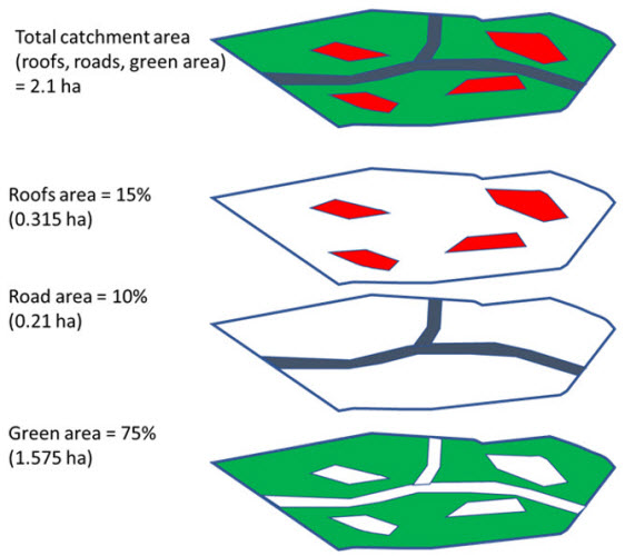
Figure: A catchment decomposed to three layers, each representing one type of catchment surface
The upper-most polygon represents the actual catchment. In the model, this catchment is represented by the three polygons below, representing roofs, roads and green areas, respectively.
These three model catchments may inherit the hydrological parameters and connections to the network, but these can also be modified to facilitate a better description of behaviour of the various surface types in the actual catchment.
In any case, the layered catchments will differ by the actual drainage area, which corresponds to the actual area of respective type of surface in the given physical catchment. The sum of the contributing areas for the three sub-catchments must equal to the actual contributing area for the catchment.
Modelling SWQ from multiple surface types as special type of boundary conditions
Surface pollution loads are defined as special types of boundary conditions to the catchments model (SWQ boundary conditions), similarly as rainfall is specified as a boundary for a precipitation-runoff model. Specifying surface pollution loads as boundary conditions, independent of rainfall boundary conditions, is necessary because spatial distributions of rainfall and of surface pollution are fully independent. Treating rainfall and surface pollution through independent boundary conditions implies that the rainfall and surface pollution can each be modelled with its own geographical distribution.
Since every SWQ boundary condition is associated with one definition of geographical location (i.e. reference to one or more catchments: All, List or Individual), and with any number of WQ boundary properties - one for any given pollutant component, each type of catchment surface must be described by a separate SWQ boundary condition. I.e. as many surface types user wants to simulate, as many stacked catchment layers and SWQ boundary conditions shall be specified.
Each of these boundary conditions shall be connected to a sub-set of catchments representing certain type of surface and would include as many WQ boundary properties as there are pollutant components associated with that type of surface - each with its own quantities (i.e. temporal variation) method.