Working with Cross Sections on the Map
Use tools from the Edit Feature toolbox on the River Network menu ribbon to insert and edit cross sections via the main Map.
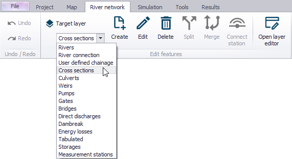
Set the ‘Target layer’ to ‘Cross sections’ and use the ‘Create’ tool to insert a cross section via the Map.
Cross sections are defined as polylines. To add a new cross section line, click firstly on the required location of the bank on one side of the river and then click at all locations of intermediate points of the polyline. To stop digitising the cross section, double-click at the location of the end point of the cross section on the other side of the river. The digitised cross section must always intersect with a river. The river name and chainage defining the location of the cross section are automatically defined by this intersection.
Each cross section is shown with two different symbologies on the map:
- The 'Cross section' symbology (by default in black) shows the total extent of the cross section
- The 'Active cross section' symbology (by default in red) shows the part of the cross section between markers 1 and 3, which is the actual cross section extent used in the simulation.
Note
The number of vertices of the polyline on the map doesn't have to match the number of survey points of the cross section, i.e. the purpose of the polyline on the map is only to represent the actual location / path of the cross section. If the survey points describe a straight line, then the polyline may be defined with only two vertices (i.e. two sets of coordinates) regardless of the number of survey points to be defined in the raw data table. Also note that inserting a cross section on the Map will set marker 1 at the first point to the left of the cross section (taking the river Flow Direction into account), marker 3 at the last point located to the right of the cross section, and marker 2 where it crosses the river line.
Cross sections that are drawn on the map will automatically be created with coordinates for each digitised points, linking them to the position specified. The use of these coordinates can be disabled in the Cross Sections editor.
Note
Cross sections with coordinates are fixed at the given location. This means that the chainage of the cross section used in the calculation may differ from the position shown on the map e.g. if the chainages have been edited after the cross sections have been drawn. To help identifying such discrepancies, it is possible to display the 'Chainage connection' layer from the 'Layers and symbols' tree, which shows the connection between the cross section and its chainage along the river. This connection line should normally remain really short. Chainages or coordinates may be updated using the tool 'Edit properties for multiple cross sections' to fix such discrepancies.
To edit a cross section on the map, use the ‘Edit’ tool and click once on the cross section on the map. The vertices of the polyline are then shown on the map, and you can click and drag these vertices to edit the location of the cross section. Clicking between two vertices will add a new vertex to the cross section.
Activate the ‘Delete’ tool and click on a cross section on the map to delete it.
Info
Tools for automatic creation of cross sections (from e.g. survey points and/or DEM) or automatic import from text files are also available in the ribbon, in the 'River network' tab.