Nodes
SWMM network nodes are hydraulic elements such as Junctions, Outfalls, Storage Units and Flow Dividers.
- Junctions are conveyance system nodes where links join together. Physically, they can represent the confluence of natural surface channels, manholes in a sewer system, or pipe connection fittings. External inflows can enter the system at junctions. Excess water at a junction can become partially pressurized during surcharge events and can either be lost from the system or be allowed to pond atop the junction and subsequently drain back through it.
- Outfalls are defined as terminal nodes of the conveyance system and used to define final downstream boundaries under Dynamic Wave flow routing. For other types of flow routing, they behave as junctions. Only one link can be incident on an outfall node.
- Storage Units are defined as conveyance system nodes that provide storage volume. Physically, they could represent something as small as a catch basin or as large as a lake. They are allowed to have any shape as described by a function or table of surface area versus height.
- Flow Dividers are defined as conveyance system nodes used to split the total flow to two outflow conduits in a prescribed manner. Flow dividers are only active under Uniform or Kinematic Wave routing and are treated as simple junctions under Dynamic Wave routing.
The SWMM network Nodes editor organizes related input data into the following groups:
- Identification. General identification and location information for the node
- Geometry. Node type and basic geometric information
- Storage Unit. Further specifications for storage unit nodes
- Outfall. Further specifications for outfall nodes
- Flow Divider. Further specifications for flow dividers
- Description. Optional descriptive information for the node.
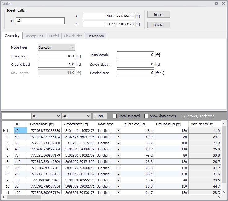
Figure: SWMM Nodes editor
Identification
Each node is geographically determined by 'x' and 'y' coordinates. The co-ordinates may be specified in any local coordinate system.
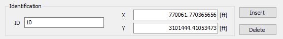
Figure: Nodes editor Identification groupbox
The Insert and Delete buttons allow addition and deletion of network elements directly in the editor, respectively.
| Edit field | Description | Used or required by simulations | Field name in data structure |
|---|---|---|---|
| ID | A unique name for the node. Up to 40 characters (letters, numbers, blank spaces and underscore characters) | Yes | MUID |
| X | X-coordinate of the node position | Yes | GeomX |
| Y | Y-coordinate of the node position | Yes | GeomY |
| Description | |||
| Description | Descriptive information related to the structure | No | Description |
| Data Source | Reference to an external data source from which the record was imported | No | DataSource |
| Asset ID | Id in the asset management system | No | AssetName |
| Status | Status from a user- specified list in the Status Codes editor | No | Element_S |
| Network Type | Type of network i.e Stormwater, Combined or separate. The list of network types can be extended by the user. Network type can be specified for each element. | No | NetTypeNo |
| Tag | Optional label used to categorize or classify the node. | No | Tag |
Table: The edit fields in the Identification group and Description tab (mss_Node)
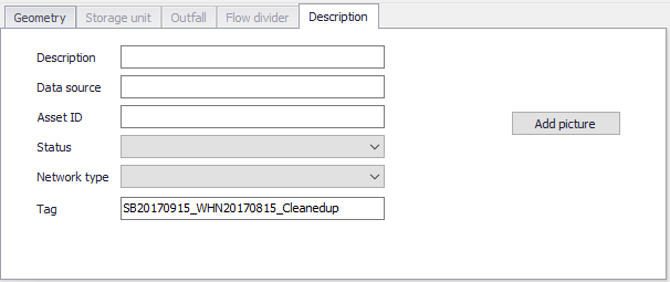
Figure: Nodes editor Description tab
Geometry
Define general node properties and geometries in the Geometry tab page of the editor.
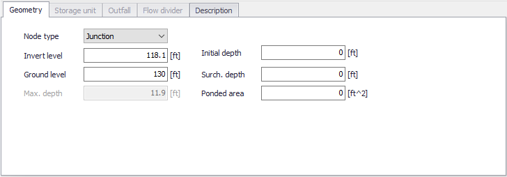
Figure: The SWMM Nodes Geometry tab
| Edit field | Description | Used or required by simulations | Field name in data structure |
|---|---|---|---|
| Node type | Definition of node as either Junction, Storage Unit, Outfall or Flow Divider | Yes | TypeNo |
| Invert Level | Invert elevation of the node | Yes | Einv |
| Ground level | Ground level of the node | Yes If Network levels specified as Absolute elevations | GroundLevel |
| Max. Depth | Maximum depth of node (i.e. from invert to ground surface) | Yes If Network levels specified as Relative depths | Dmax |
| Initial Depth | Initial depth of water at the node at the start of the simulation | No | D0 |
| Surch. Depth | Additional depth of water beyond the maximum depth that is allowed before the junction floods. This parameter can be used to model Bolted/Sealed manholes | No | Dsur |
| Ponded Area | Area occupied by ponded water atop the junction after flooding occurs. If the Allow Ponding analysis option is turned on, a non-zero value of this parameter will allow ponded water to be stored and subsequently returned to the conveyance system when capacity exists. Default is allow ponding is not turned on. | No | Apond |
Table: The edit fields in the SWMM Nodes Geometry tab (mss_Node)
Storage Unit
Define input parameters for storage units in the Storage Unit tab page of the Nodes editor.
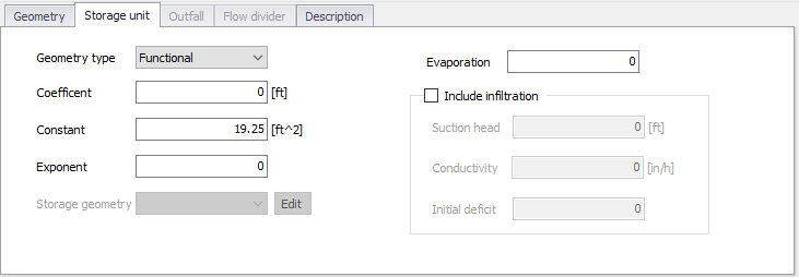
Figure: The SWMM Nodes Storage Unit tab
The Geometry Type defines how the geometry of storage unit is specified. The geometry of a Storage Unit can be defined with the following formats.
- Cylindrical. This option defines the storage unit with vertical sides and an elliptical base. The equation for the base area is
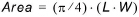 , where L and W are the base major axis length and base minor axis length, respectively. If only the area is known but not the lengths, use the 'Functional' type instead.
 - Conical. This option defines the storage unit with a truncated elliptical cone shape. The equation for the surface area is
 , where L and W are the base major axis length and base minor axis length, respectively, and Z is the side slope (run / rise) of a vertical slice through the major axis.
 - Parabolic. This option defines the storage unit with an elliptical parabooid shape. The equation for the surface area is
 , where L and W are the major axis length and minor axis length at height H, respectively. If only the area is known but not the lengths, use the 'Functional' type instead.
 - Pyramidal. This option defines the storage unit with a truncated rectangular pyramid or a rectangular box shape. The equation for the surface area is
 , where L and W are the base length and width, respectively, and where Z is the side slope (run / rise) (which should be 0 for a box). Each side wall has the same angle from vertical.
 - Functional. This option uses the following function to define the geometry by computing for surface area from water depth, D:

- From curve. This option uses a storage area-depth table defined in the Curves and Relations editor to define the geometry of the storage unit.
As an example, a Storage Unit whose cross-sectional area remains constant with depth (e.g. a cylinder or cube) can be described by a FUNCTIONAL geometry type whose coefficient equals the cross-sectional area and whose exponent is 0.
| Edit field | Description | Used or required by simulations | Field name in data structure |
|---|---|---|---|
| Geometry Type | Definition of the type of geometry description of the Storage Unit | Yes | GeomTypeNo |
| Coefficient | Coefficient for the Functional relationship between storage depth and surface area | Yes, if Functional is chosen | GeomCoeff |
| Exponent | Exponent for the Functional relationship between storage depth and surface area | Yes, if Functional is chosen | GeomExponent |
| Constant | Constant value for the Functional relationship between storage depth and surface area | Yes, if Functional is chosen | GeomConst |
| Major length | Largest length of the horizontal area | Yes, if Cylindrical, Parabolic, Conical, or Pyramidal shape is chosen | MajorLength |
| Minor length | Smallest length of the horizontal area | Yes, if Cylindrical, Parabolic, Conical, or Pyramidal shape is chosen | MinorLength |
| Side slope | Slope of the vertical walls (run / rise) | Yes, if Conical or Pyramidal shape is chosen | Slope |
| Axis height | Height of the parabolic shape | Yes, if Parabolic shape is chosen | Height |
| Evaporation | Fraction of potential evaporation realized | No | Fevap |
| Storage Geometry | ID of the tabular geometrical description. The geometry is specified relative to the invert level. This ensures reusability of the geometry for different Storage Units with different inverts | Yes if From Curve is chosen | GeomID |
| Include Infiltration checkbox | Option to apply optional Green-Ampt infiltration parameters so that the storage unit can serve as an infiltration basin | Yes | StorageInfiltrationNo |
| Suction Head | Average value of soil capillary suction along wetting front | Yes, if Infiltration is included | StorageSuctionHead |
| Conductivity | Soil saturated hydraulic conductivity | Yes, if Infiltration is included | StorageConductivity |
| Initial Deficit | Fraction of soil volume that is initially dry | Yes, if Infiltration is included | StorageInitialDeficit |
Table: Edit fields in the SWMM Nodes Storage Unit tab (mss_Node)
Outfall
Definition of an outfall in an urban drainage network is optional for uniform flow (UF) and Kinematic Wave (KW) routing.
However, when applying Dynamic Wave routing, at least one outfall in the urban drainage system must be defined. It is possible to select between five types of outfalls:
- Free Outfall. Bases the outfall stage on the smaller of the critical and normal depths of flow in the connecting conduit.
- Normal Depth. Uses just the normal depth of flow.
- Constant Stage. Uses a constant water elevation at all times.
- From Tide Curve. Has outfall stage varying in a repeating fashion over a tidal period.
- Time Series. Allows variation of the outfall stage in a specified manner over time.
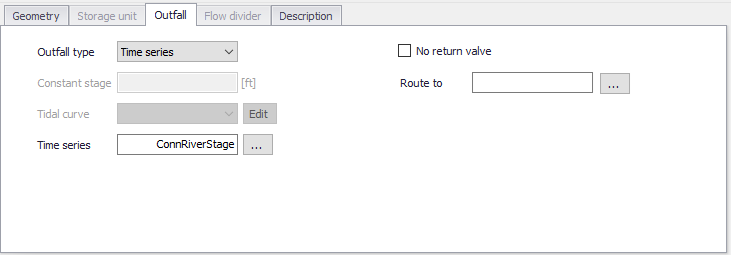
Figure: SWMM Nodes editor Outfall dialog
| Edit field | Description | Used or required by simulations | Field name in datastructure |
|---|---|---|---|
| Outfall Type | Type of outfall | Yes | FlapGateTypeNo |
| Constant Stage | Fixed position of tide gate | Yes if Outfall is of type Constant Stage | FixedStage |
| Tidal Curve | Outfall stage as a function of hour of day over a complete tidal cycle. Curve is specified in Curves and Relations | Yes if Outfall is of type From Tide Curve | TideGateID |
| Time Series | Outfall stage variation over time. | Yes if Outfall is of type Time Series | TideGateTSID |
| Non Return Valve | Option for defining a non-return valve preventing backwater | No | FlapGateNo |
| Route To | Option for leading the outflow discharge to another sub-catchment | No | RouteTo |
Table: Edit fields in the Nodes Outfall dialog (mss_Node)
Flow Divider
Flow divider nodes can be one of the following types:
- Overflow. All flow above the non-diverted conduits full flow depth is diverted
- Cutoff Flow. All flow above the cutoff level is diverted.
- From Curve. A curve is supplied that specifies the amount of diverted flow to total flow.
- Weir. The diverted flow is linearly proportional to the total flow in excess of some minimum flow
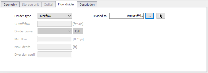
Figure: SWMM Nodes editor Flow Divider dialog
| Edit field | Description | Used or required by simulations | Field name in datastructure |
|---|---|---|---|
| Divider Type | Type of Divider | Yes, if Junction Type is Flow Divider | DividerTypeNo |
| Divided To | The ID of the link that receives the diverted flow | Yes | LinkID |
| Cutoff Flow | Cutoff flow value used for a Cutoff Flow divider | Yes, if Divider Type is Cutoff Flow | CutoffFlow |
| Divider Curve | ID of diversion flow series for a From Curve divider | Yes, if Divider Type is From Curve | DivertedFlowID |
| Min. Flow | Minimum flow at which diversion begins for a Weir divider | Yes, if Divider Type is Weir | DivertedMinFlow |
| Max. Depth | Maximum depth above invert at which proportional diversion continues for a Weir divider | Yes, if Divider Type is Weir | DivertedMaxDepth |
| Diversion Coeff | Coefficient which determines what fraction between the min. and max. flows the diverted flow will be given the fraction that current water depth is of the max. depth for a Weir divider | Yes, if Divider Type is Weir | DivertionCoeff |
Table: Edit fields in the Flow Divider dialog (mss_Node)