Weirs
A weir is actually a functional relation, which connects two nodes of a MIKE 1D urban network (two-directional flow and submerged flow possible), or is associated with only one node (free flow 'out of the system'). The latter case is achieved if the 'To' field is left empty.
Real urban sewer systems configure a weir to be located in a manhole or a similar construction which you normally would define as a node in the digital model. The numerical solutions for the flow equations, however, need a model configuration with two nodes where the weir is defined as the connection between the nodes. The weir will then be placed between the two nodes as the flow connection.
It is possible to define several weirs between the same two nodes if this is required. This is similar to the possibility of having more than one pipe as the link between nodes. The generation of the computational grid shown in model configuration of orifice is also applied for pumps, weirs and valves. The numerical solution of the flow equations will depend on the selected device. Please refer to the reference manual on more on this.
It is recommended not to place the two nodes in the same spot, instead place the nodes a short distance apart. The reason is that the node head loss computation will have a component from change of flow direction. If the two nodes surrounding the device are placed exactly at the same location then the computational engine cannot determine the direction of the flow from the coordinates of the nodes and a default direction will be applied. This may unintentionally introduce a change in direction and therefore also an unexpected head loss.
By using a small displacement of the nodes the change in flow direction will be determined based on the coordinates and angles between the connected pipes. Therefore consider carefully the placement of the nodes with respect to the actual construction.
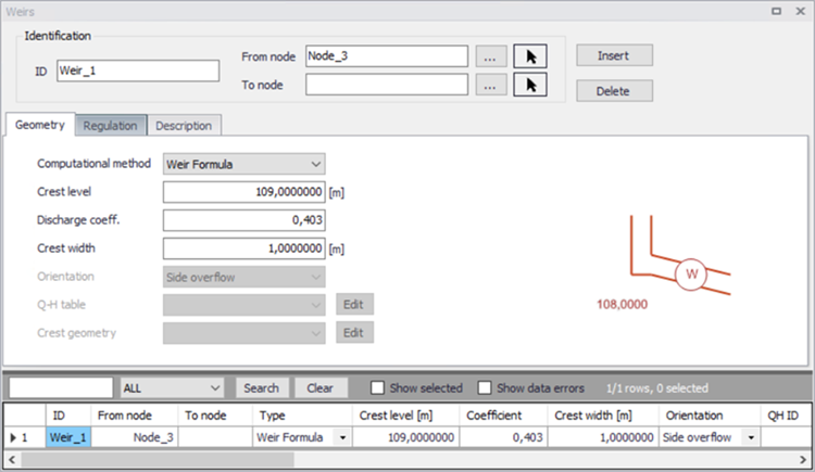
Figure: Weirs editor
A weir is primarily characterised by its computational method, i.e. equation type, which can be:
- Weir formula: with this method, the weir is described with a crest level, a discharge coefficient and a crest width, using the Overflow formula (broad crested weir).
- Energy loss coefficient: with this method, the weir is described with a crest level, a crest width and an orientation, using the Overflow formula (broad crested weir). The orientation plays an important role, since depending on the specified orientation, kinetic energy of the flow is included (90o) or excluded (0o) in calculations of the weir flows.
- Q-H: with this method, the weir is described with a crest level and a Q-H table, using the QH structure formula.
- CRS weir formula: with this method, the weir is described with a crest level, a discharge coefficient and a crest geometry, using an orifice formula.
Weirs are per default static (No control) but can be controlled using control rules. When 'Controlled by control rules' is selected, the weir crest level may be controlled during the simulation using control rules (unless the weir is a Q-H type weir).
There are no limitations on the number of weirs specified at one location.
Identification and connectivity
| Edit field | Description | Used or required by simulations | Field name in data structure |
|---|---|---|---|
| Description | User's descriptive information related to the weir | No | Description |
| Data source | Reference to an external data source (table ID) where the record has been imported from | No | DataSource |
| Asset ID | Reference to an ID used in external data sources | No | AssetName |
| Status | Data status for the entire record, serves for keeping track on the source of information | No | Element_S |
| Network type | Attributes the weir to a certain type of network. Used in cases when two or more different networks are included in the same project | No | NetTypeNo |
| Weir ID | A unique name for the weir. Up to 40 characters (letters, numbers, blank spaces and underscore characters) | Yes | MUID |
| From node | ID of Node where Weir is located | Yes | MUID |
| To node | ID of Node where Weir is discharging to. If field left empty, then water is discharging out of the system | Yes | MUID |
| Apply | This check box allows to toggle the Active status of the weir on and off. The simulations will omit all weirs that are not active. | Yes | Enabled |
Table: Description (Table msm_Weir)
Model data
| Edit field | Description | Used or required by simulations | Field name in data structure |
|---|---|---|---|
| Computational method | Selection of computation Method | Yes | MethodNo |
| Crest level | Crest level of weir | Yes | CrestLevel |
| Discharge coeff. | Discharge coefficient | Yes, if weir formula is chosen | Coeff |
| Crest width | Width of rectangular weir | Yes, if weir formula is chosen | CrestWidth |
| Orientation | Weir orientation relative to the main flow direction. “0” is Side weir, “90” is a transversal weir | Yes, if discharge coeff. is not specified | AngleNo |
| Q-H table | Reference to tabulated Q-H funtion | Yes, if Q-H is chosen | QHID |
| Crest Geometry | Reference to tabulated variation of the weir crest along the weir, CRS geometry | Yes | WeirCrestID |
| Non return flap | Flap indicating a flap-gate built-in weir (i.e. no return flow possible) | Yes | FlapNo |
| Controlled by control rules | If selected, the weir is controlled using control rules as defined in the ‘Control rules’ editor. Control rules will apply only when both this check box and the ‘Apply’ check box in the control rule definition are ticked. Note that the regulation with control rules is always disabled, when the 'Control rules' module is unselected in the 'Model type' editor. | Yes, if control rules apply | ControlTypeNo |
| Max level | The maximum elevation of a movable weir crest | Yes, if control rules apply | MaxCrestLevel |
| Min level | The minimum elevation of a movable weir crest. The fixed weir is not used with control rules | Yes, if control rules apply | MinCrestLevel |
| Max speed up | The maximum velocity for movement of the weir in upward direction | Yes, if control rules apply | MaxCrestLevelIncreaseSpeed |
| Max speed down | The maximum velocity for movement of the weir in downward direction | Yes, if control rules apply | MaxCrestLeveldecreaseSpeed |
Table: Weir Geometry and Regulation (Table msm_Weir)