Real Time Control
General description
Real time control provides the following operations:
- Variable pump speed to maintain pressure or level or flow/velocity set-points
- Movement of valves to maintain pressure or level or flow/velocity set-points.
The purpose of this kind of control is to provide generic way of moving valves and changing pump speed other than what is done using IF-THEN-ELSE rules or VSD pump control. IF-THEN-ELSE rules control valves and pumps instantly (at the time step) and may result, in some cases, in oscillating solutions in between time steps. Or, in case of VSD pump control, they may not be able to operate more than 1 pump within the same zone due to interference of the algorithm with other pumps. The presented real-time control provides an independent mechanism that can be used to determine or simulate pump or valve operations in a physical system.
The real-time control provides two algorithms:
- Linear control
- PID (Proportional – Integral – Derivative) control.
Linear control is a mechanism that will increase or decrease the control setting based on the actual value of the measured process variable versus the set-point. The position of a control valve will be increased or decreased and the pump speed will be increased or decreased. The increase and decrease rates as well as the maximum and minimum settings are pre-defined.
PID (Proportional – Integral – Derivative) control is a control loop feedback mechanism (controller) commonly used in industrial control systems. A PID controller continuously calculates an error value e(t) as the difference between a desired set point and a measured process variable. The controller attempts to minimize the error over time by adjustment of a control variable u(t), such as the position of a control valve or a pump speed to a new value determined by a weighted sum:
(6.1) 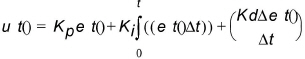
Where Kp, Ki, and \(K_{d}\) are all non-negative coefficients for the proportional, integral, and derivative terms. In this model:
- \(K_{p}\) accounts for present values of the error. For example, if the error is large and positive, the control output will also be large and positive.
- \(K_{i}\) accounts for past values of the error. For example, if the current output is not sufficiently strong, error will accumulate over time, and the controller will respond by applying a stronger action.
- \(K_{d}\) accounts for possible future values of the error, based on its current rate of change.
Real Time Control Editor
A list of the Real Time Control attributes follows, with a short description given for each one.
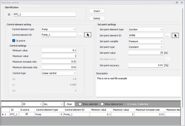
Figure: The Real Time Control editor
Identification
The ID is the main identifier of the real-time control.
Control element settings
- Control element type: This data entry allows you to define the type of a controlled element: pump, or a TCV valve.
- Controlled element ID: This data entry allows you to define the ID of the controlled element. You can select the element from a list by clicking the '…' button.
- Is active: This check box allows the user to toggle the Active status of the control on and off. The simulations will omit all controls that are not active.
- Minimum value: This data entry allows you to define the minimum control value (relative pump speed or valve opening percentage).
- Maximum value: This data entry allows you to define the maximum control value (relative pump speed or valve opening percentage).
- Maximum increase rate: This data entry allows you to define the maximum rate at which the variable can increase. In units of the control variable (relative pump speed or valve opening percentage per minute.
- Maximum decrease rate: This data entry allows you to define the maximum rate at which the variable can decrease. In units of the control variable (relative pump speed or valve opening in %) per minute.
- Control type: This data entry allows you to choose between the linear control or PID control (Proportional-integral-derivative control).
- Kp: In case of PID control, this data entry allows you to define the proportional constant (proportional gain).
- Ki: In case of PID control, this data entry allows you to define integral constant (integral gain).
- Kd: In case of PID control, this data entry allows you to define derivative constant (derivative gain).
Set-point settings
- Set point element type: This data entry allows you to select the type of the set point element such as a tank or a junction node, or a pipe.
- Set point element ID: This data entry allows you to define the ID of the set point node.
- Set point variable: This data entry allows you to define type of the set-point variable. In case of a tank or a junction (set-point element type) the set-point variable can be “Grade – hydraulic gradeline” or “Level” (in case of tanks), or “Pressure” in case of a junction node. In case of a pipe (set-point element type) the set-point variable can be “Flow” or “Velocity”.
- Set-point type: This data entry allows you to define the type of a set-point value a “Constant” or “Variable”.
- Set point value: In case of a constant set-point, this data entry allows you to define the set-point value.
- Set point curve: In case of a variable set-point, this data entry allows you to define the curve ID defining how the set point value changes in time. Note, that the curve (table) definition is done in the Curves Editor.
- Set-point accuracy: This data entry allows you to define the accuracy of the algorithm (control) in percentage of the set-point.
Description
This field allows to specify a user-defined description of the control entry.
Remarks
The program uses the following predefined valve characteristics tau curves in case of TCV valve control:
- Quick opening valve (gate)
- Globe valve
- Plug valve
- Butterfly valve
- Ball valve
- Equal percentage 5%.
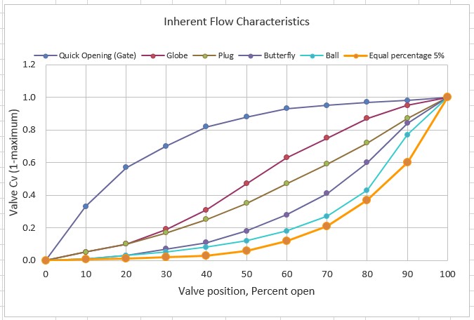
Figure: Default valve characteristics