Valves
Valves control the flow or pressure of water from one junction node to another. The functionality and setting of the valve is defined by it Valve Type setting. Valves are represented as links of negligible length. Note that valve pressure settings are pressures (e.g., psi or m above node elevation) and not total head (or hydraulic gradeline elevation).
Valves are either defined interactively on the Map using the 'Drawing' tool on the Edit tab with Valves selected as the Layer to edit, or by manual data entry using the Valve editor. Valves cannot be directly connected to reservoir or storage tank nodes.
The Valve editor allows to define the valve's ID, type, status, nodal connectivity, description, and other attributes.
Valve Properties
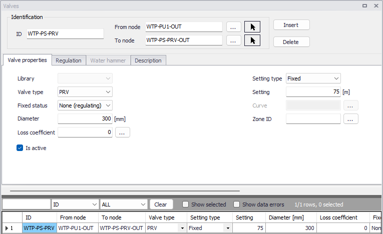
Figure: Valve properties editor
The 'Insert' button creates a new valve. 'Delete' removes the selected valve.
ID
This data entry is used to specify an ID which uniquely identifies the valve in the database. The valve ID acts as a unique look up key that identifies this link from all other links. A link can be a pipe, valve, pump or turbine. Therefore, no two links may have the same ID. However, a node and a link (i.e., junction or reservoir) can have the same ID. The valve ID value can be any string value (up to 40 characters).
From Node, To Node
These data entries define the ID of the valve's starting (upstream) and ending (downstream) nodes. These IDs define the valve connectivity of the network.
Choosing '...' will display the Select Node dialog box from which the user can select the appropriate node. Valves cannot be directly connected to reservoir or storage tank nodes. Choosing the arrow allows the user to graphically select the node from the Map window.
Controlled flow is always assumed from the starting (upstream) node to the ending (downstream) node. Some valve types act as Check valves and does not allow flow from the To Node to the From Node. If the computed flow is moving from the ending node to the starting node, the computed flow value will be negative.
Valve type
This menu specifies the functionality of the valve. There are six different options.
- PRV: A Pressure Reducing Valve limits the pressure at the downstream node to not exceed a preset value as long as the upstream node pressure is above the PRV setting. If the upstream pressure is below the setting, flow through the valve is unrestricted. Should the pressure at the downstream node exceed the pressure at the upstream node, the valve closes to prevent reverse flow. Note that PRVs cannot be placed directly in series. This valve requires a specified pressure (in m or ft at downstream node elevation) as setting. Pressure reducing valves can be based on the fixed pressure set-point or a set-point that is related to the actual flow, i.e. flow modulated.
- PSV: A Pressure Sustaining Valve attempts to maintain a minimum pressure at the upstream node when the downstream node pressure is below the PSV setting. If the downstream pressure is above the setting, flow through the valve is unrestricted. Should the downstream nodal pressure exceed the upstream nodal pressure, then the valve closes to prevent reverse flow. Note that PSVs cannot be placed directly in series. This valve requires a specified pressure (in m or ft at upstream node elevation) as setting.
- PBV: A Pressure Breaker Valve forces a specified pressure loss to occur across the valve. Flow can be in either direction through the valve. This valve requires a specified loss (in m or ft) as setting.
- FCV: A Flow Control Valve limits the flow through a valve to a specified amount. The program will produce a warning message if this flow cannot be maintained with the current head at the upstream node of the valve. This valve requires a flow to be specified as setting.
- TCV: A Throttle Control Valve is used to simulate partially closed valves by adjusting the minor head loss coefficient of the valve. This valve type requires a relationship between the degree to which the valve is closed and the resulting head loss coefficient. These are created and edited under Tables > Curves and relations. The Curve type is Valve characteristics Cd. The curves for a few characteristic valves are available in MIKE+ as default. Other curves can usually be obtained from the valve manufacturer. An initial opening percentage or Loss coefficient must also be specified as setting. Regulation or Rule-based control can be used to change this percentage setting during an extended period simulation, and thereby get another head loss coefficient from the curve.
- GPV: A General Purpose Valve provides the capability to model devices and situations with unique headloss - flow relationships, such as reduced pressure backflow prevention valves, turbines, and well drawdown behaviour. The valve requires a relationship curve between flow and head loss. These are created and edited under Tables > Curves and relations. The Curve type is Valve head loss.
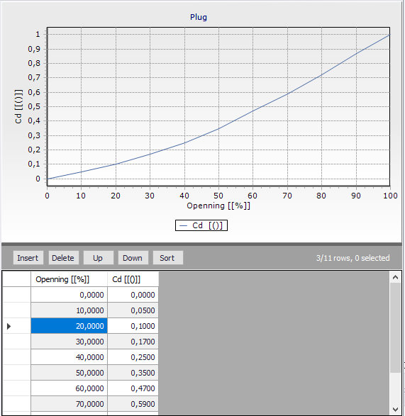
Figure: Example of TCV curve
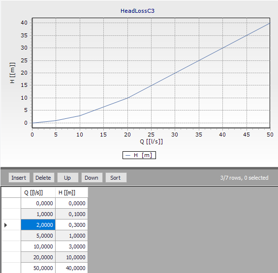
Figure: Example of GPV curve
Fixed status
This drop down list allows the user to toggle the OPEN and CLOSED status of the valve. Choosing CLOSED effectively removes the valve from the network system.
Diameter
This data entry defines the internal diameter of the valve, in the unit of your choice.
Loss coefficient
This data entry defines the sum of all the minor (or local) loss coefficients for the valve when fully opened, not including losses in TCV valve. The Loss coefficient is unitless. Choosing "..." will display Select Minor Loss Coefficient selection dialog box, allowing the user to select the appropriate minor loss coefficient to use. If more that one minor loss component exists along the valve, then the sum of the corresponding minor loss coefficients should be entered.
Is active
This check box data entry allows the user to toggle the Active status of the valve on and off. The simulations will omit all valves that are not active.
Setting type
Only available for TCV Valves or PRV Valves. Two options for the valve setting are available for TCV valves:
- Opening
- Loss coefficient.
This option allows to choose to set a Opening % value for the valve, which is converted to a Loss coefficient using the specified Curve, or to set a Loss coefficient directly in the setting field.
Two options for the valve setting are available for PRV valves:
- Fixed
- Flow modulated.
The second option allows the user to choose a pressure vs flow curve for the valve, The pressure vs flow curve is defined in the 'Curves and relations' editor.
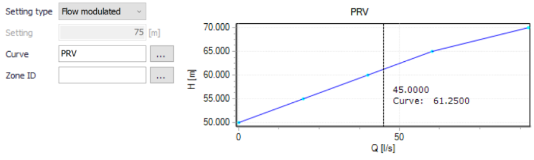
Figure: Defining a flow-modulated PRV valve
Setting
The valve setting. This data entry defines the pressure setting for PRVs, PSVs, and PBVs, whose units are in psi or m. Or, this data entry defines the flow settings (in user-defined flow units) for FCVs, or % opening or loss coefficients for TCVs.
When defining a pressure setting, the value specified is pressure at Node elevation (e.g., psi or m) and not total head (or hydraulic gradeline elevation).
Curve
The user must specify a Curve for PRV, TCV or GPV valves. [...] opens the Curve ID selector. A curve of type Valve characteristics Cd should be specified for a TCV valve and a Valve head loss curve should be specified for a GPV valve. Both curve types are generated from Tables > Curves and relations.
Zone ID
This is an optional name for the zone to which the valve belongs. When a zone ID is specified, this zone will be listed in the 'Zones' editor. The '…' button can be used to select an existing zone.
Level control
Only available for TCV valves. It allows the valve to gradually open and close based on the water level in the inlet tank. The valve's intermediate position, between the fully open and fully closed position, is determined using a valve curve and the actual water level in the tank (between the level open and close). The following settings must be specified.
- Tank ID: this is the inlet tank ID.
- Level open: this is the water level in the tank when the valve is fully open.
- Level close: this is the water level in the tank when the valve is fully close.
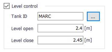
Figure: Example of level control for a TCV valve
Regulation
The regulation tab allows to set simple rules for controlling each valve, depending on the pressure level in a node or tank, time of day or time since simulation started.
The tab has three parts. The middle contains a grid for all rules that controls the active valve. This window also allows to add or remove control rules for the valve.
The left window is the editor for the active control rule, currently selected in the grid.
The right window displays a time series if there are rules based on Time conditions.
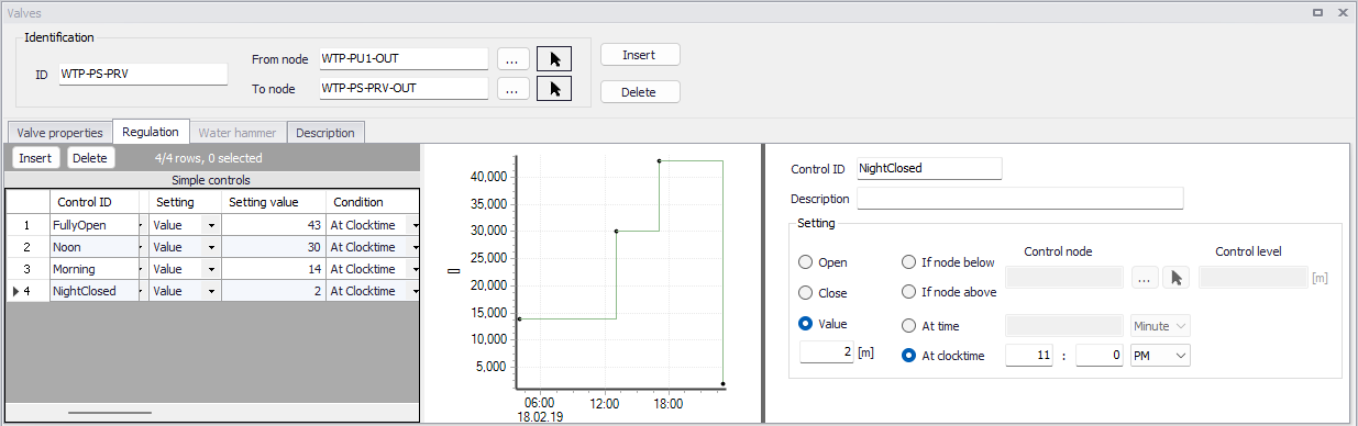
Figure: Regulation tab
Pressing 'Insert' in the middle window creates a new control rule for the selected valve. 'Delete' removes the active control rule. The properties and settings for the active rule is displayed in the left part of the regulation tab.
Control ID
An ID for the rule is automatically generated, but could be specified by the user. Note that every Control ID for all pipes, pumps, valves and turbines in the model must be unique.
Description
This field allows users to type text to describe the Control.
Setting
The settings contain three parts:
- Action
- Type of condition
- Condition.
A radio button is used to set an Action. A valve can only be set to Open, Close or a Value. The Value correspond to the Valve setting (on Valve properties tab) and changing the Value effectively means changing the setting. The function and unit depends on the valve type of the controled valve.
A radio button is used to set Condition type to one type of condition that will trigger the action:
- If node below/above... This rule will execute the action if the pressure level in a specified node is above or below a specified level.
- At time... This rule will execute the action when the specified amount of time since simulation start has passed. When setting up a series of these rules there will be a time series of the setting in the right window.
- At clocktime... This rule will execute the action every day at the specified time.
The available Condition settings will depend on the selected condition type:
- When “If node below/above” is selected, the user must specify a node or tank ID in the first field and the threshold pressure level in the second field. Note that this is defined as the pressure at Elevation level for a node, and the pressure at Base elevation for a tank.
- When “At time” is selected, the user must specify a number and a time unit (hours/minutes) since start of simulation.
- When “At clocktime” is selected the user must specify a time of day in hours, minutes and AM/PM.
Water hammer
Control valves can be simulated under hydraulic transient conditions, with the following valve types:
- TCV (throttle control valves)
- PRV (pressure reducing valves)
- PSV (pressure sustaining valves / back pressure valves)
- PBV (pressure breaker valves)
- FCV (flow control valves).
The additional settings are described below.
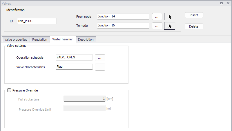
Figure: The Water hammer tab from the Valves editor
Operation schedule
This is the ID of a curve providing the relationship between the valve opening (in %) as a function of time. This curve is specified in the 'Curves and relations' editor, and must be defined with the curve type 'Valve operation schedule'. The program will use it to set the initial valve opening at the start of the simulation.
Valve characteristics
This is the ID of a curve providing the relationship between the valve coefficient Cd as a function of the valve opening (in %). This curve is specified in the 'Curves and relations' editor, and must be defined with the curve type 'Valve characteristics Cd'. The program will use it to move the valve during the transient flow to maintain the valve set point (valve settings).
Full stroke time
This is a positive float number representing the time for the valve to move from fully open to fully closed position.
Pressure override
The 'Pressure override' option allows to open the valve when the pressure on the valve inlet side exceeds the specified 'Pressure override limit' pressure value. This allows to simulate e.g. a pressure relief valve during the hydraulic transient flow conditions. Note, that this requires to connect the downstream side of such a valve to the fixed level reservoir representing a wet valve where the pressure relief valves can discharge the water. To simulate a pressure relief valve, set the valve operational schedule (time series) to close and the program will open it when the valve becomes active. The valve opening and closing time depends on the full stroke time settings. When the inlet pressure drops below the 'Pressure override limit' value, the valve will return to the fully closed position.
This option is only available when using the newest version of the Water Hammer engine, in the 'Model type' editor.
Pressure override limit
This is the pressure value controlling the opening and closing of the valve, when the 'Pressure override' option is used.
Note
The 'Water hammer analysis' option must be selected in the 'Model type' editor, for this tab to be enabled in the 'Valves' editor.
Description
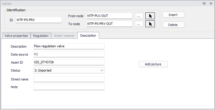
Figure: The Description tab from the Valves editor
Description
This data entry allows to enter a description for the selected valve.
Add picture
The 'Add picture' button allows to add photo for a individual valve. Once loaded from external source, the picture will be displayed on this tab.
Data source
This data entry is used to specify a corresponding asset data source (such as database table or a database file name), in the asset management system.
Asset ID
This data entry is used to specify a corresponding asset ID, which uniquely identifies the valve in the asset management system (such as GIS, for example).
Status
This drop down selection list data entry allows you to define whether the valve is imported (i.e existing node was imported from the external data source), or is inserted, modified, GIS, calibrated or similar. By default, the status is undefined.
Street name
This field is used to define the street name. This is an optional field and can be used for better navigation through the pipe network and for reporting purposes.
Attributes
Attributes from the database are summarized in the table below.
| Field | Database name | Description | Mandatory? | Default value |
|---|---|---|---|---|
| ID | MUID | Identifier, must be unique for all link types including valves etc | Yes | Labels are generated in sequential order |
| From node | FromNodeID | The from node of the valve, defining the start | Yes | |
| To node | ToNodeID | The to node of the valve, defining the end | Yes | |
| Valve type | TypeNo | The type of valve. | Yes | PSV |
| Fixed status | StatusNo | Open/ close setting | None | |
| Diameter | Diameter | Inside diameter of valve | Yes | 50 mm |
| Loss coefficient | LossCoeff | The sum of all minor losses within the valve. | No | |
| Is active | Set the valve active/inactive | Yes | TRUE | |
| Setting type | SettingNo | Setting type for TCV valve | For TCV | Loss Coefficient |
| Curve | HLCurveID | The Curve ID for TCV or GPV. | For TCV or GPV | |
| Setting | Setting | Valve setting. The unit and interpretation depends on valve type. | For PSV, PRV, PBV, FCV, and TCV | |
| Description | Description | Descriptive text | No | |
| Data source | DataSource | Text field for data source. | No | |
| Asset ID | Asset | Text field to identify the valve to the corresponding valve in the asset management system. | No | |
| Street name | StreetName | Text field to define street name. | No |
Table: Valve attributes