Pipes
Pipes are used to transport water from one node to another. Pipes must always begin and end at a node.
Pipes are either defined interactively on the Map window using the 'Drawing' tool on the Edit tab with Pipes selected as the Layer to edit, or by manual data entry using the Pipe Editor dialog box.
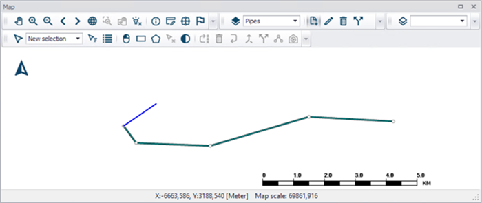
Figure: Pipes displayed in map
Geometry
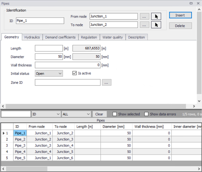
Figure: Pipe Geometry tab
The 'Insert' button creates a new pipe. 'Delete' removes the selected pipe.
ID
This specifies the unique identifier of the pipe. The pipe ID acts as a unique look up key that identifies this link from all other links. A link can be a pipe, valve, pump or turbine. Therefore, no two links may have the same ID. However, a node and a link (i.e., junction or reservoir) can have the same ID. The pipe ID value can be any string value (up to 40 characters).
From Node, To Node
These define the ID of the pipe's starting (upstream) and ending (downstream) nodes. These IDs define the pipe connectivity of the network.
Clicking '...' will display the Select Node dialog box from which the user can select the appropriate node. The Node Type pull-down selection list allows the user to specify what type of node is connected to the end of the pipe. Choosing the arrow allows the user to graphically select the node from the Map window.
The order matters since the sign of the computed flow is moving from the starting node to the ending node, the computed flow value will be positive. If the computed flow is moving from the ending node to the starting node, the computed flow value will be negative.
Length
This data entry defines the pipe length, in the unit of your choice. The second (greyed out) field shows the length based upon the pipe layout. It is also possible to define a specific pipe length, independent of the pipe network layout that will be used if specified.
Diameter
This data entry defines the internal diameter of the pipe, in the unit of your choice. The second field (read-only) displays the pipe diameter as it would be used for the hydraulic analysis. The pipe diameter is automatically adjusted when the pipe wall is defined.
Wall thickness
This field is used to define the wall thickness of a pipe. The pipe diameter is automatically adjusted by the program when the pipe thickness is defined.
Initial Status
This drop down list allows the user to toggle the OPEN and CLOSED status of the pipe. Choosing CLOSED effectively removes the pipe from the network system. This is also where the user can define the presence of a check valve (CV) in the pipe. If a check valve exists, then water is only allowed to flow from the starting to ending node. This is commonly used to prevent a flow reversal through the pipe. If conditions exist for flow reversal, the valve shuts and the pipe carries no flow.
Note
You cannot set the pipe status of a pipe containing a check valve using regulation. Pipes with a check valve are initially open, and close only if flow within the pipe attempts to reverse (move from the ending downstream node to the starting upstream node).
Is active
This check box allows the user to toggle the Active status of the pipe on and off. The simulations will omit all pipes that are not active.
Zone ID
This is an optional name for the zone to which the pipe belongs. When a zone ID is specified, this zone will be listed in the 'Zones' editor. The '…' button can be used to select an existing zone.
Hydraulics
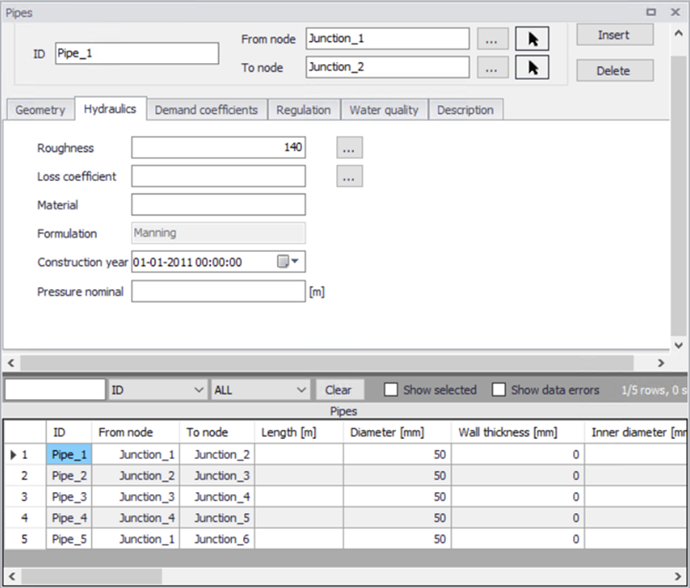
Figure: Pipe Hydraulics tab
Roughness
This data entry defines the roughness of the interior surface of the pipe. Based upon which head loss type has been specified for the project, this value is unit less for Hazen-Williams or Chezy-Manning headloss formulas, and in millifeet or mm for the Darcy-Weisbach (or Colebrook-White) formulation. The “...” button will open the roughness coefficient selection window, allowing the user to select the appropriate roughness value to use for pre-defined materials.
The head loss formulation is displayed in the ‘Formulation’ field below, for information. It can be specified by the user in the ‘General settings | Model type’ editor.
Loss coefficient
This data entry defines the sum of all the minor (or local) loss coefficients for the pipe, which are unitless. Choosing "..." will display Select Minor Loss Coefficient selection dialog box, allowing the user to select the appropriate minor loss coefficient to use. If more that one minor loss component exists along the pipe, then the sum of the corresponding minor loss coefficients should be entered.
Material
This option allows the user to define the material of pipe construction. The Pipe Material is defined as a "string" a string and does not influence calculations. The friction losses in hydrodynamic calculations are based on pipe roughness, which can be globally assigned based upon the pipe material and pipe construction year, for example.
Formulation
This read only field displays the head loss setting. It can be specified by the user within the Simulation specification > Hydrodynamic simulation settings, where the Head losses setting is changed on the HD parameters tab.
Construction year
This option allows the user to define the age of the pipe. Pipe age is defined as a date. Clicking the Calendar opens a calendar dialogue where the user can browse to a date.
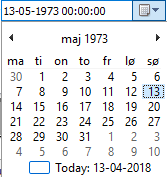
Figure: Calendar view
Demand coefficients
MIKE+ allows the user to distribute a specified water demand to the network based upon a variety of pipe properties. Three methods are available from the Distributed Demand tool (found in the Tools ribbon). This feature is useful for automatically assigning the nodal water demand to a large network, since the software will automatically proportion the total network demand based upon predefined pipe properties. These methods are used to mimic the amount of actual demand along a pipe, based upon the pipe length or pre-defined demand coefficients.
- Method of equal pipe lengths, distributes the demand based on pipe length and the pipe diameter.
- Method of reduced pipe length, distributes the demand based on pipe length and a user specified coefficient.
- Method of reduced Two Coefficients, distributes the demand based on two user specified coefficients.
The Method of reduced pipe length and method of two coefficients uses one or two user specified pipe coefficients. More information about these calculations are found in the chapter Distributed Demand tool.
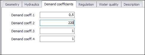
Figure: Pipe Demand Coefficients tab
Demand coefficient 1 - 4
Fields for specifying coefficients relevant to pipe leakage. A higher number will generate a larger portion of the total demand to be distributed.
Note that there are four fields but no more than two coefficients can be selected in a Distributed demand calculation. The coefficients that is used is specified in the Distributed demand tool.
Regulation
The regulation tab allows to set simple rules for controlling each pipe to open or close, depending on the pressure level in a node, time of day or time since simulation started.
The tab has three parts. The middle contains a grid for all rules that controls the active pipe. This window also allows to add or remove control rules for the selected pipe.
The left window is the editor for the active control rule, currently selected in the grid.
The right window displays a time series if there are rules based on Time conditions.
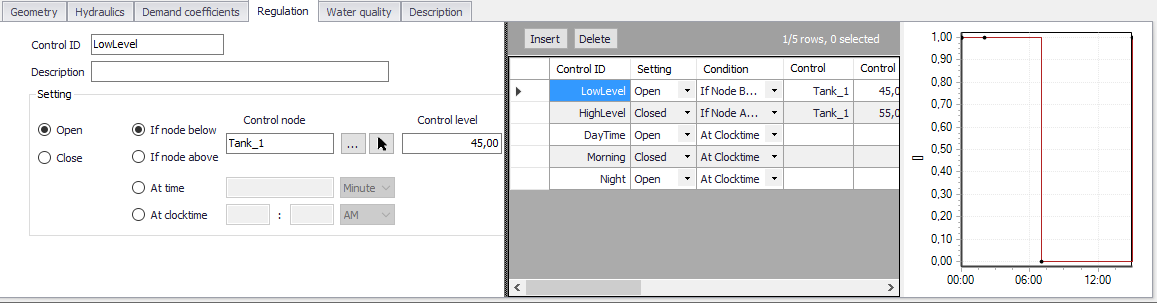
Figure: Regulation tab
Pressing 'Insert' in the middle window creates a new control rule for the selected pipe. 'Delete' removes the active control rule. The properties and settings for the active rule is displayed in the left part of the regulation tab.
Control ID
An ID for the rule is automatically generated, but could be specified by the user. Note that every Control ID for all pipes, pumps, valves and turbines in the model must be unique.
Description
This field allows users to type text to describe the Control.
Setting
The settings contain three parts:
- Action
- Type of condition
- Condition.
A radio button is used to set an Action. A pipe can only be set to Open or Close.
A radio button is used to set Condition type to one type of condition that will trigger the action:
- If node below/above... This rule will execute the action if the pressure level in a specified node is above or below a specified level.
- At time... This rule will execute the action when the specified amount of time since simulation start has passed. When setting up a series of these rules there will be a time series of the setting in the right window.
- At clocktime... This rule will execute the action every day at the specified time.
The available Condition settings will depend on the selected condition type.
- When “If node below/above” is selected, the user must specify a node or tank ID in the first field and the threshold pressure level in the second field. Note that this is defined as the pressure at Elevation level for a node, and the pressure at Base elevation for a tank.
- When “At time” is selected, the user must specify a number and a time unit since start of simulation.
- When “At clocktime” is selected the user must specify a time of day in hours, minutes and AM/PM.
Water quality
This tab allows for each pipe to have locally defined reaction rates. Please refer to section on Water Quality reaction rates for further information.
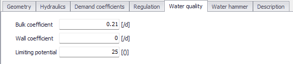
Figure: Water Quality tab
Bulk coefficient
This data entry defines the bulk reaction rate that is applied to flow in the pipe. Units for bulk reaction rates are in 1/day.
Wall coefficient
This data entry defines the pipe wall reaction rate that is applied to flow in the pipe. Units for pipe wall reaction rates are in 1/day.
Limiting potential
This setting specifies that reaction rate is proportional to the difference between the current concentration and some limiting value. When undefined, the program will use the global limiting potential specified in water quality settings of the 'Simulation setup' editor.
Description
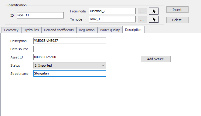
Figure: Pipe Description tab
Description
This data entry allows you to enter a description for the selected pipe.
Add picture
The 'Add picture' button allows to add photo for a individual pipe. Once loaded from external source, the picture will be displayed on this tab.
Data source
This data entry is used to specify a corresponding asset data source, which identifies the pipe (such as database table or a database file name) in the asset management system.
Asset ID
This data entry is used to specify a corresponding asset ID, which uniquely identifies the pipe in the asset management system (such as GIS, for example).
Status
This drop down selection list data entry allows you to define whether the pipe is imported (i.e existing node was imported from the external data source), or is inserted, modified, GIS, calibrated or similar. By default, the status is undefined.
Street name
This field is used to define the street name. This is an optional field and can be used for better navigation through the pipe network and for reporting purposes.
Attributes
Attributes from the database are summarized in the table below.
| Field | Database name | Description | Mandatory? | Default value |
|---|---|---|---|---|
| ID | MUID | Identifier, must be unique for all link types including valves etc | Yes | Labels are generated in sequential order |
| From node | FromNodeID | The from node of the pipe, defining the start | Yes | |
| To node | ToNodeID | The to node of the pipe, defining the end | Yes | |
| Length | L | Pipe length | No | |
| Diameter | Diameter | Diameter of pipe | Yes | 50 mm |
| Wall thickness | Thickness | Wall thickness of pipe to calculate inner diameter | No | |
| Initial status | StatusNo | Sets the pipe to open, closed or check valve | Yes | Open |
| Is active | Enabled | Set the pipe active/inactive. | TRUE | |
| Roughness | RCoeff | Defines the interiour surface roughness. The unit depends on the headloss formula. | Yes | |
| Loss coefficient | LCoeff | The sum of all minor losses within the pipe. | No | |
| Material | Material | Text field for pipe material. Not used in calculations. | No | |
| Construction year | CDate | Date to describe pipe age. Not used in calculations. | No | |
| Demand coeff. 1-4 | Coeff1 Coeff2 Coeff3 Coeff4 | Coefficient for demand distribution calculations. | No | |
| Bulk coefficient | Bulk_Coeff | Locally defined reaction rate in water quality calculations. | No | |
| Wall coefficient | Wall_Coeff | Locally defined reaction rate for water quality calculations. | No | |
| Description | Description | Descriptive text | No | |
| Data source | DataSource | Text field for data source. | No | |
| Asset ID | Asset | Text field to identify the pipe to the corresponding pipe in the asset management system. | No | |
| Street name | StreetName | Text field to define street name. | No |
Table: Pipes attributes