Extended Rule-Based Controls
Rule-Based Controls allow link status and settings to be based on a combination of conditions that might exist in the network over an extended period simulation. Rule-based controls will be either in the form of an action clause or a condition clause.
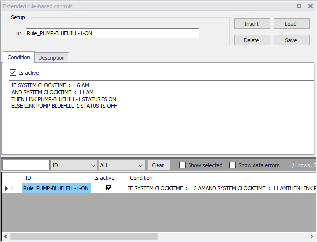
Figure: The Extended rule-based control editor
The following buttons are available at the top of the editor:
- Insert: Insert a new rule.
- Delete: Delete a rule.
- Load: Load rules from a text file (*).
- Save: Save rules into a text file (*).
(*) You can edit the rules within the ASCII file and import them back to MIKE+ by selecting Load from ASCII file. This is convenient in cases when you use Excel or other tools to create the list of rules for the model.
Format of rules
General format
Each rule is a series of statements of the form:
IF condition_1
AND condition_2
OR condition_3
AND condition_4
etc.

THEN action_1
AND action_2
etc.

ELSE action_3
AND action_4
etc.

PRIORITY value
where:
- conditon_n is a Condition clause
- action_n is an Action clause
- priority is a priority value (e.g., a number from 1 to 5).
Remarks:
- Keywords IF, AND, OR, THEN, ELSE, PRIORITY must always start at a new line.
- Only the RULE, IF and THEN portions of a rule are required; the other portions are optional. The "RULE" portion is automatically created from the contents of Rule ID and Description fields. The portions "IF" (i.e. condition clause) and "THEN" (i.e. action clause) must be provided by the user.
- When mixing AND and OR clauses, the OR operator has higher precedence than AND, i.e.,
IF A or B and Cis equivalent toIF (A or B) and C- If the interpretation was meant to be
IF A or (B and C)then this can be expressed using two rules as in
IF A THEN ...
IF B and C THEN ...
- The PRIORITY value is used to determine which rule applies when two or more rules require that conflicting actions be taken on a link. A rule without a priority value always has a lower priority than one with a value. For two rules with the same priority value, the rule that appears first is given the higher priority.
- The decimal separator for numerical values must be a point.
Condition clause
A condition clause in a Rule-Based Control takes the form of:
where:
- object is a category of network object
- id is the object's ID label
- attribute is an attribute or property of the object
- relation is a relational operator
- value is an attribute value
Some example conditional clauses are:
JUNCTION 23 PRESSURE > 20
TANK T200FILLTIME BELOW 3.5
LINK 44 STATUS IS OPEN
SYSTEM DEMAND >= 1500
SYSTEM CLOCKTIME = 7:30 AM
The Object keyword can be any of the following:
- NODE
- LINK
- SYSTEM
- JUNCTION
- PIPE
- RESERVOIR
- PUMP
- TANK
- VALVE.
When SYSTEM is used in a condition no ID is supplied.
The following attributes can be used with Node-type objects:
- DEMAND
- HEAD
- PRESSURE
The following attributes can be used with Tanks:
- LEVEL
- FILLTIME (hours needed to fill a tank)
- DRAINTIME (hours needed to empty a tank)
These attributes can be used with Link-Type objects:
- FLOW
- STATUS (OPEN, CLOSED, or ACTIVE)
- SETTING (Pump speed or Valve setting)
- LIKE (See Multiple Pumps, Valves with LIKE setting for more details)
- STARTTIME (hours from the last pump start)
- STOPTIME (hours from the last pump stop)
The SYSTEM object can use the following attributes:
- DEMAND (total system demand)
- TIME (hours from the start of the simulation)
- CLOCKTIME (24-hour clock time with AM or PM appended)
Relation operators consist of the following:
=IS<>NOT<BELOW>ABOVE<=>=
Action clause
An action clause in a Rule-Based Control takes the form of:
where
- object is LINK, PIPE, PUMP, or VALVE keyword
- id is the object's ID label
- value is a status condition (OPEN or CLOSED), pump speed setting, or valve setting
Some example action clauses are:
Multiple Pumps, Valves with LIKE setting
The LIKE setting allows to control multiple pumps or valves in efficient way. It is possible to set a pump speed to x % of another pump, for example. Such an option could also be used when the new value is the value of the object itself (e.g. to set a pump speed to increase by 20 %, or valve to open by 10 % and so on).
The default values for the B (multiplier) and C (increment) are B=1, C=0 and they do not need to be provided.
The setting value is calculated as:
Example 1
The pump 3 setting will be set equal to the settings of the pump 4 (multiplier= 1 and increment = 0) at time 8 am.
Example 2
The pump 3 setting will be higher by 10% than the settings of the pump 4 (multiplier = 1.10 and increment = 0) at time 8 am.
Example 3
The valve 10 setting (PRV setting, for example) will be lower by 10 (pressure units) than the settings of the valve 20 (multiplier = 1 and increment = -10) at any time (12 AM is the simulation start).
Example 4
The pump 3 status (OPEN, CLOSED) will be set equal to the status of the pump 4 at any time (12 AM is the simulation start).
Example 5
If pump 3 setting is equal to the settings of the pump 4 (default multiplier = 1 and increment = 0) then …
Controls Examples
Control of a valve
This set of rules opens and closes a valve based on the water level in a storage tank.
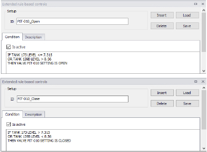
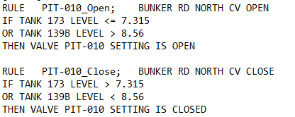
Figure: Rules in EPANET .inp file
Control of a pump
This set of rules opens and closes a pump based on the water level in a storage tank.
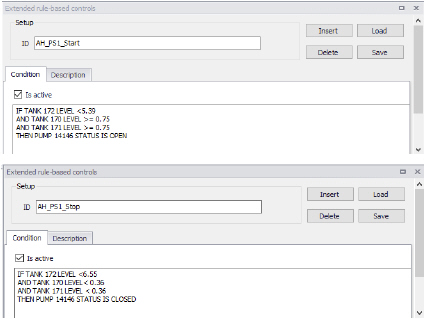
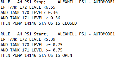
Figure: Rules in EPANET .inp file