Orifices
An orifice is actually a functional relation, which connects two nodes of a MIKE 1D urban network or is associated with only one node (free flow 'out of the system'). The latter case is achieved if the 'To node' field is left empty.
In real urban systems a flow restriction in the form of an orifice may be located in a manhole or a similar construction which you normally would define as a node in the model configuration. The numerical solutions for the flow equations, however, need a model configuration with two nodes where the orifice is defined as the connection between the nodes. The orifice will then be placed between the two nodes as the flow connection.
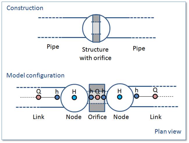
Figure: The difference between real world orifice and model configuration of orifice
It is possible to define several orifices between the same two nodes if this is required. This is similar to the possibility of having more than one pipe as the link between nodes. The generation of the computational grid shown in the figure above for the orifice is also applied for pumps, weirs and valves. The numerical solution of the flow equations will depend on the selected device. Please refer to the reference manual on more on this.
It is recommended not to place the two nodes in the same spot, instead place the nodes a short distance apart. The reason is that the node head loss computation will have a component from change of flow direction. If the two nodes surrounding the device are placed exactly at the same location then the computational engine cannot determine the direction of the flow from the coordinates of the nodes and a default direction will be applied. This may unintentionally introduce a change in direction and therefore also an unexpected head loss.
By using a small displacement of the nodes the change in flow direction will be determined based on the coordinates and angles between the connected pipes. Therefore consider carefully the placement of the nodes with respect to the actual construction.
An orifice is specified by a type; circular, CRS or rectangular, and the corresponding diameter, height and width.
A discharge coefficient can be specified (default = 1.0) and a non-return flap can be specified.
Orifices are per default static (No Control) but an orifice can be controlled by control rules. Selecting the 'Controlled by control rules option', the opening of weirs / gates in orifices can be controlled during the simulations
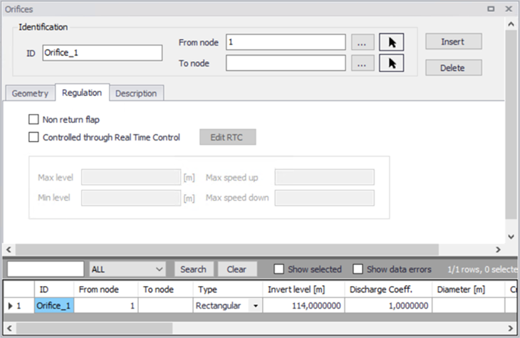
Figure: Orifice editor
Identification and connectivity
| Edit field | Description | Used or required by simulations | Field name in data structure |
|---|---|---|---|
| Description | User's descriptive information related to the orifice | No | Description |
| Data source | Reference to an external data source (table ID) where the record has been imported from | No | DataSource |
| Asset ID | Reference to an ID used in external data sources | No | AssetName |
| Status | Data status for the entire record, serves for keeping track on the source of information | No | Element_S |
| Network type | Attributes the link to a certain type of network. Used in cases when two or more different networks are included in the same project | No | NetTypeNo |
| Orifice ID | A unique name for the orifice. Up to 40 characters (letters, numbers, blank spaces and underscore characters) | Yes | MUID |
| From node | ID of Node where orifice is located | Yes | FromNodeID |
| To node | ID of Node where orifice is discharging to. If field left empty, then water is discharging out of the system | Yes | ToNodeID |
| Apply | This check box allows to toggle the Active status of the orifice on and off. The simulations will omit all orifices that are not active. | Yes | Enabled |
Table: Description (Table msm_Orifice)
Model data
| Edit field | Description | Used or required by simulations | Field name in data structure |
|---|---|---|---|
| Type | Type of orifice according to shape, being rectangular, circular or CRS | Yes | TypeNo |
| Diameter | Diameter of circular orifice | Yes | Diameter |
| Height | Height of rectangular orifice | Yes | Height |
| Width | Width of rectangular orifice | Yes | Width |
| Discharge coeff | Calibration coefficient. Value = 1 results in the flow as determined by orifice algorithm | Yes | DischargeCoeff |
| Invert level | Absolute elevation of the orifice invert | Yes | InvertLevel |
| CRS Geometry ID | Reference of a cross-section ID for irregularly-shaped orifice | Yes, if CRS type is chosen | CrsID |
| Non return flap | Flap indicating a flap-gate built-in (i.e. no return flow possible) | Yes | FlapNo |
| Controlled by control rules | If selected, the orifice is controlled using control rules, as defined in the 'Control rules' editor. Control rules will apply only when both this check box and the 'Apply' check box in the control rule definition are ticked. Note that the regulation with control rules is always disabled, when the 'Control rules' module is unselected in the 'Model type' editor. | Yes | ControlTypeNo |
Table: Geometry (Table msm_Orifice)
Defining a gate or a weir in an orifice
The orifice itself is just an opening with a static shape. In real constructions orifices are often equipped with a controlled gate or weir which can be used in real time control for regulating the flow through the orifice. The gate device will move from the top of the orifice opening and downwards until the orifice is fully closed. The weir moves from the bottom of the orifice upwards and closes fully when the weir crest reaches the top of the orifice opening (see figure below for an illustration). It is possible to apply both types of movable devices in the computations. In both cases the device is “added” to a defined orifice. This is done from the “Control Rules” dialog.
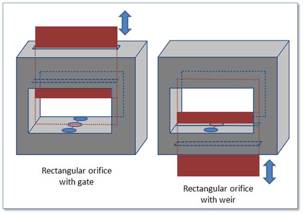
Figure: Examples on a rectangular orifice with a gate and a weir