Controls
Control rules are used to define how pumps and regulators are controlled based on simulation time or conditions at specific nodes and links.
The Controls editor organizes the related input data into the following groups:
- Identification. Identification and description
- Control Rules. Built from combinations of conditions and actions and are defined in the input box
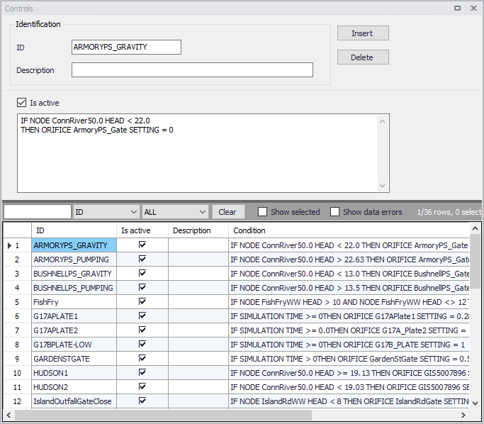
Figure: The SWMM Controls editor
| Edit field | Description | Used or required by simulations | Field name in datastructure |
|---|---|---|---|
| ID | ID of the specific rule | Yes | MUID |
| Description | User's descriptive information related to the node | No | Description |
| Is Active | Option for activating/deactivating a control rule during a simulation | Yes | Enabled |
Table: Edit fields in the SWMM Controls editor
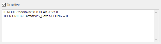
Figure: Control rules input box
Define control rules in the dialog dividing the lines into Conditions and Actions. Please note there can only be either a Condition or an Action in one line. Build control rules as combinations of conditions and actions using the following elements:
| Elements | Description | Used or required by simulations |
|---|---|---|
| Operator | IF, AND, OR, THEN, ELSE | Yes |
| Object | Node, Link, Pump, Orifice, Weir or Simulation | Yes |
| Object ID | ID of the object | Yes |
| Attribute | Depth, Head, Inflow, Flow, Setting, Time, Date, Clocktime | Yes |
| Relation | =, \<, >, \<>, \<=,>= | Yes |
| Value | Value | Yes |
Table: Elements for building control rules