Coupling Tools
In the Coupling Tools menu ribbon (activated when the 2D Overland Hydrodynamic module is turned on), tools are available for defining and editing 1D-2D couplings.
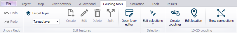
Figure: The Coupling Tools menu ribbon
Create Couplings
The Create Couplings tool is used to configure couplings between 1D and 2D model elements. New coupling definitions are created using this tool, with new rows with unique IDs automatically generated in the 1D-2D Couplings editor table.
Tip
If you intend to couple your model in several steps, you can dock the 'Create couplings' window within your workspace for easier access (e.g. besides the map or besides the '1D-2D couplings' editor).
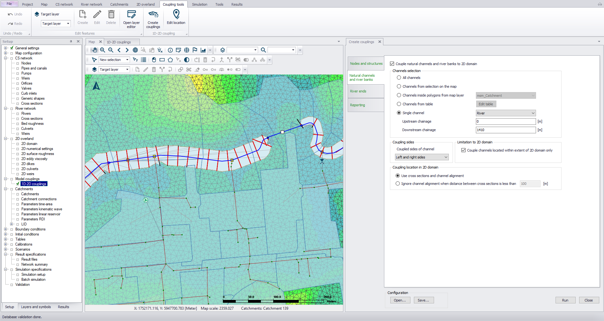
Figure: Docking the Create Couplings tool window in the workspace
Nodes and Structures
The first tab in the Create Couplings tool dialog enables coupling of nodes and structures to 2D models. Tick on the option ’Couple nodes and structures to 2D domain.”
For ‘Rivers, collection systems and overland flows’ model types, the tool offers tab pages for coupling other model components to the 2D domain (e.g. Natural channels and river banks). If only couplings to item types other than nodes and structures are needed, leave this option inactive.
When working with ‘SWMM5 collection system and overland flows’ model types, only options for coupling nodes and structures to the 2D domain are available.
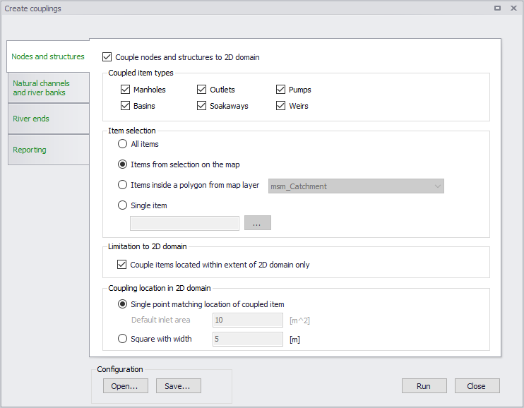
Figure: Couple nodes and structures using the Create Couplings tool
Coupled Item Types
Select the node or structure components to be coupled. The item types offered vary depending on the type of collection system model being used in the project (e.g. SWMM5).
Tip
Every time the Create Couplings tool is executed, coupling definitions are added to the 1D-2D Couplings editor table, so one may define couplings incrementally.
Item Selection
A number of options are available for defining which individual 1D items are to be coupled:
- All items: Creates coupling definitions for all components of the selected item types, e.g. all manholes.
- Items from selection on the map: Select nodes, pumps or weirs (depending on the selected coupled item types) via the Map view or network item editor overview table which will be selected on the Map. The currently active selection will be coupled.
- Items inside a polygon from map layer: Limit the coupling to items that are located within an area (e.g. within a catchment). This area defined by a polygon feature must be part of the model (e.g. msm_Catchment data layer) or loaded into the model as a background layer and selected.
- Single item: Only couple one node or structure. In this case, click on the ellipsis button (…) to specify the ID of the element to be coupled.
Limitation to 2D Domain
Tick on the ‘Couple items located within extent of 2D domain only’ option to ensure that only nodes and structures within the 2D domain are considered when coupling (recommended).
Coupling Location in 2D Domain
Define how couplings are to be spatially defined:
- Single point matching location of coupled item: The coupling is defined with the coordinates of the coupled item, except for weirs and pumps for which they are defined at the location of the upstream node (i.e. From node). During the simulation, this item will be coupled to the 2D cell in which it lies.
- Square with width: This will couple the node/structure to 2D cells with centers geographically within the square with specified dimensions around the node/structure location. In this case, more than one 2D cell/element may be coupled to a1D item, and the flow will be distributed among the cells when flowing from the 1D item. This feature is useful if one expects high flow exchanges that may cause computational instabilities.
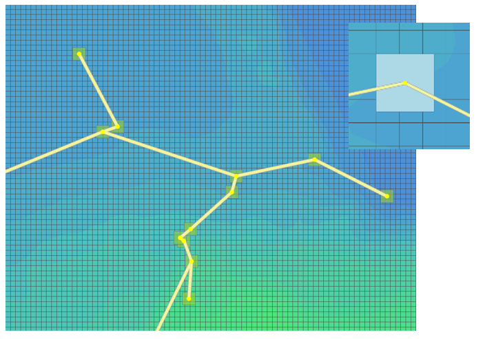
Figure: Coupling 2D cells by square area with defined width
A default inlet area is assigned to the created couplings. In 'Rivers, collection system and overland flows' mode, the default area for couplings to manholes is the area of the manhole computed using its diameter, and for couplings to basins or soakaways it is obtained from the node's geometry curve. In 'SWMM5 collection system and overland flows' mode:
- With the option 'Single point matching location of coupled item', the default inlet area of the inlet is manually specified in the 'Default inlet area' field.
- With the option 'Square with width', the default inlet area is computed using the specified square's width.
It is always possible to manually edit the inlet area of individual couplings afterwards, from the '1D-2D couplings' editor.
Natural Channels and River Banks
Another tab in the Create Couplings tool enables natural channels and river banks to be coupled to 2D domains. Tick on the ’Couple natural channels to 2D domain’ to activate this option.
If only couplings to item types other than natural channels and rivers are needed, leave this option unticked.
Note
Coupling SWMM5 open channels' banks to 2D overland domain is not supported.
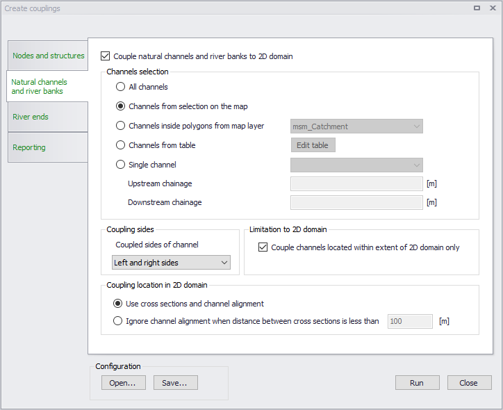
Figure: Couple natural channels and river banks using the Create Couplings tool
Channels Selection
A number of selection methods are available for defining channels to be coupled:
- All channels: Creates a coupling definition for every natural channel (specified in the CS network | Pipes and Canals editor) or river (specified in River network | Rivers or in MIKE HYDRO).
- Channels from selection on the map: Select channels via the Map or network feature overview tables. Selecting items in editor overview tables will select/highlight the corresponding items on the Map. The currently active selections will be coupled.
- Channels inside polygons from map layer: Limit the coupling to items within an area (for example a catchment) defined by a polygon. This polygon feature must be part of the model (msm_Catchment) or loaded into the model as a background layer to be selected.
- Channels from table: Click on the ’Edit table’ button to import individual or all natural channels (specified in CS network | Pipes and canals) or river branches (specified in River network | Rivers or in MIKE HYDRO) and tick on/off the channels to be coupled. Alternatively import a list of channels in text format via the ’Import from file’ option. The text file must contain three columns with the upstream chainage value, the downstream chainage, and the channel ID. The columns should be space-delimited and provided in this order.
- Single channel: Only couple one channel. In this case, select the ID of the channel to be coupled as well as which section of the channel to couple (upstream and downstream chainage of the channel).
Coupling Sides
Natural channel/river bank coupling allows a string of cells/elements to be laterally linked to a given channel link section (between specified upstream and downstream chainages) or an entire natural channel.
The user must specify whether the actual linkage is to be made along the ’right side’ of the channel, the ’left side’, or the ’left and right sides’. In the latter case, two couplings will be created.
Limitation to 2D Domain
To ensure that only channels that lie within the 2D domain are considered when coupling (recommended), tick on the option ’Couple channels located within extent of 2D domain only”. When a channel is partly within the 2D domain but extends beyond the 2D domain borders, the coupling is created only within the extent of the 2D domain.
Coupling Location in 2D Domain
Determination of which 2D element faces are to be coupled is made based on the extents of cross sections along channels. Two methods can be used:
- Use cross-sections and channel alignment: The location of the coupling line is based on the extent of the cross sections in the river reach. as well as on the direction of the channel. A vertex is added to this coupling line at each cross section location, and at each change of direction (i.e. at each vertex) of channel. This method ensures that the coupling follows the channel's direction between cross sections, which is convenient when the distance between cross sections is long compared to the channel's width.
- Ignore channel alignment when distance between cross sections is less than a specified distance: The location of the coupling line is solely based on the extent of the cross sections in the river reach. The coupling line has a straight shape between two consecutive cross sections. This method is convenient when the distance between cross sections is small compared to the channel's width, as the number of cross sections is sufficient to correctly define the bank's location.
The determination of which 2D cells/elements are to be coupled is then made from the coupling line. The flow from/to the 1D channel is coupled and distributed to the closest faces of the mesh along this line.
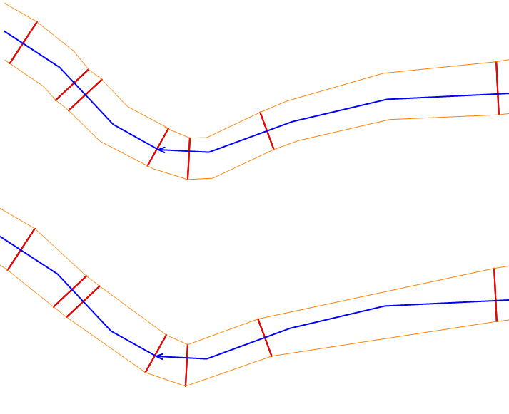
Figure: Bank coupling location in 2D domain using (at the top) and ignoring (at the bottom) channel alignment
River Ends
The third tab in the Create Couplings tool enables ends of rivers to be coupled to the 2D overland model by ticking on the ’Couple river ends to 2D domain’ option. If only coupling to other item types than river ends are needed, leave this option unticked.
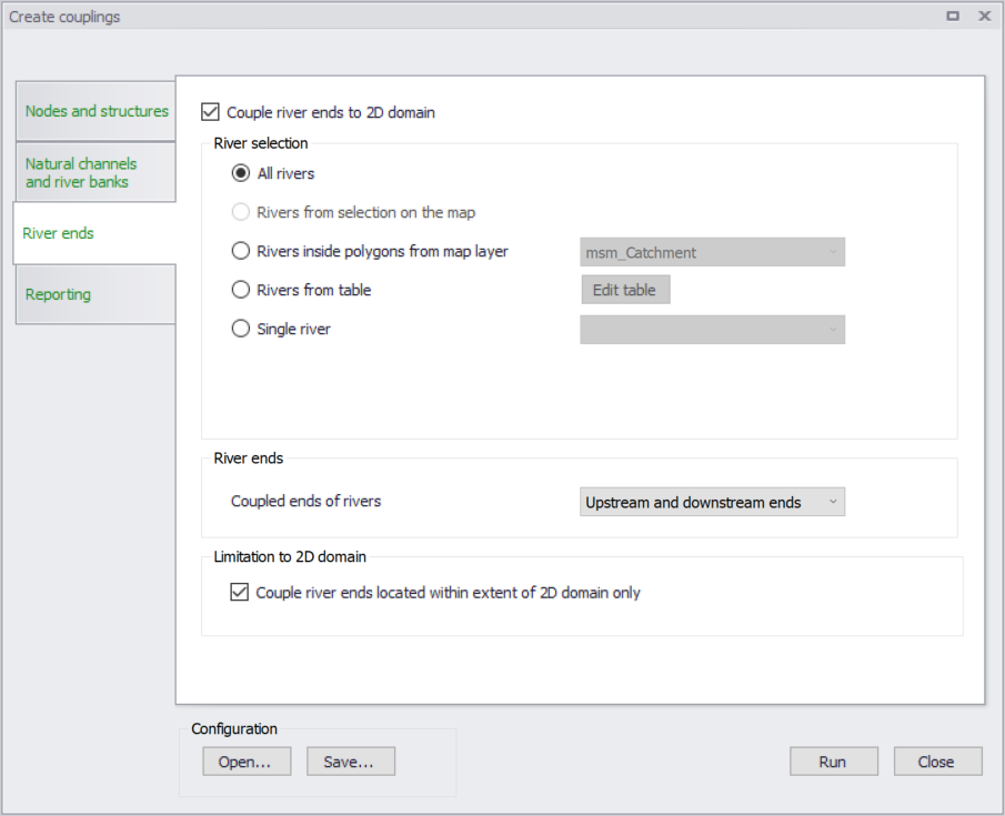
Figure: Couple river ends using the Create Couplings tool
River Selection
A number of selection methods are available for defining which rivers to couple:
- All rivers: Creates a coupling definition for all rivers (specified in River network Rivers or in MIKE HYDRO).
- Rivers from selection on the map: Select rivers via the Map or Rivers editor table, and the currently active selection will be coupled (Option not available with MIKE HYDRO).
- Rivers inside polygons from map layer: Limit the coupling to rivers that are located within an area (for example a catchment). This area defined by a polygon must be part of the model (e.g. msm_Catchment data layer) or loaded into the model as a background layer to be selected.
- Rivers from table: Click on the ’Edit table’ button to select which rivers to couple. Alternatively import a list of channels in text format via the ’Import from file’ option. The text file must contain two space-delimited columns with a value representing the coupled end (1 for Upstream, 2 for Downstream) and the river ID.
- Single river: Only couple one river. In this case, select the ID of the river to be coupled.
River Ends
The user must specify whether the linkage is to be made at the upstream or downstream end of the rivers, or both. In the latter case, two couplings will be created.
For the ’Rivers from table’ option, this choice is ignored and is overridden by the selections made in the table.
Limitation to 2D Domain
To ensure that only the river ends lying within the 2D domain are considered when coupling (recommended), tick on ’Couple river ends located within extent of 2D domain only’.
Reporting
Once a coupling configuration is run, a summary of the coupling will be reported in this section of the tool. This report can be saved for further inspection.
Configuration
Use the ‘Save’ button to save configuration settings in *.XML format for reuse later or in another model.
The ‘Open’ button loads a previously-saved configuration file.
Once your configuration is complete, run the tool using the ’Run’ button to create your couplings.
Edit Location
The Edit Location tool is used for editing existing couplings between 1D and 2D model elements. The tool replicates the functionality of the Create Couplings tool, but unlike the 'Create couplings' tool, this tool will update the location (i.e. coordinates) of existing coupling definitions in the 1D-2D Couplings editor.
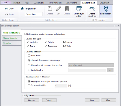
Figure: The Edit Location tool
This tool enables fast updating of locations for multiple coupling items at once. Batch editing of couplings may be especially useful when computation instabilities are encountered in the integrated model due to high flow exchanges through couplings. The tool may be used to distribute flow from 1D model elements to more 2D cells/elements and reduce flow velocities over the coupled cells/elements.
Edit, Delete
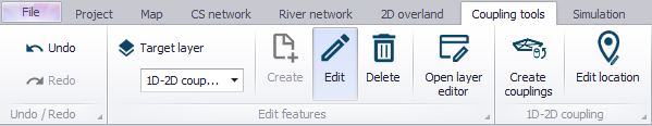
Figure: Edit and Delete tools on the Coupling Tools menu ribbon
The locations of couplings can be manually edited on the Map. Set ‘1D-2D couplings' as the target layer in the Edit Features toolbox on the Coupling Tools menu ribbon and activate the 'Edit' button.
Click on a coupling feature on the Map to edit its location. For a point coupling, it is possible to drag the coupling to a new location. For a line or polygon coupling, vertices can be added, deleted, or moved.
Couplings can also be deleted from the Map using the 'Delete' button and clicking on the desired coupling feature.
It is not possible to create new couplings from the Map.