Interpolation and Assignment Tool
Introduction
The field assignment and interpolation tool is a tool that will assign values to any field in the MIKE+ database either by taking the attribute value directly from another feature/attribute or by interpolating between a number of other features.
Examples of the tasks that may be performed with this tool are:
- Assign ground elevation values from a raster layer representing the DEM to nodes.
- Assign the diameter of manholes to be equal to the largest pipe entering the manhole.
- Calculate missing values for manhole invert levels from a point theme using Inverse Distance weighted spatial interpolation
- Calculate pipe levels by interpolating values following the network (pipes).
- Assign a value to a construction year and or contractor based upon a polygon theme giving city areas.
The source of the data (i.e. the features where data is taken from) may be any layer in the MIKE+ map view, including layers that have been added as background layers. Any compatible data value can be assigned to almost any field in the database. This also means that it should be used with some care as it obviously also can make completely non-sense assignment if the wrong fields or names are specified.
The tool is accessed through the MIKE+ ribbon, WD network or CS network tab (depending on the project mode), Network Editing Tools, Interpolation and assignment.
The tool is set up as a workflow with the following steps:
- Target selection
- Assignment Method
- Assignment options (depending on the method chosen)
- Overall assignment
- Reporting
Each of the above steps are described in detail in the following sections.
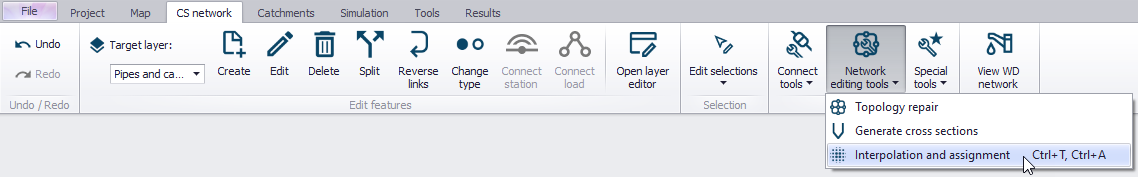
Figure: Accessing the interpolation and assignment tool
Target Selection
In the first step of the workflow, select the target attribute for the assignment. A target map layer (network component) must first be selected followed by a target attribute from the selected network component. For example, nodes layer, ground level attribute.
Once the empty fields are populated, MIKE+’s data validation functionality changes the “Target Selection” section of the workflow heading colour from red to green.
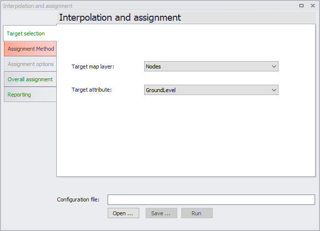
Figure: The Target selection dialog
Assignment Method
The next stage of the workflow defines the method to assign values to the target and the data source.
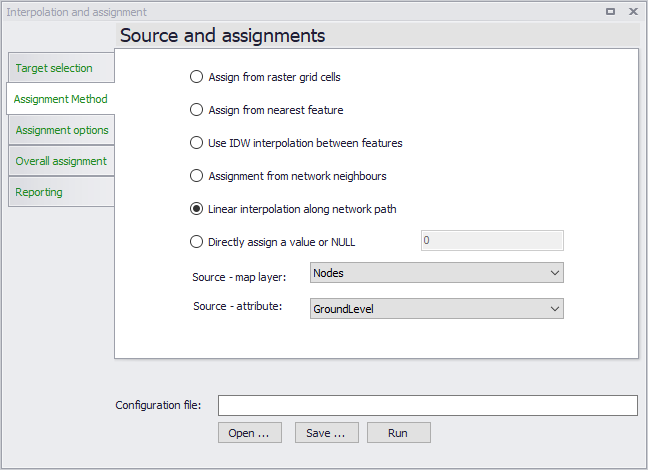
Figure: The Assignment Method dialog
First you must select the method as this will influence the valid choices for the data source. A number of methods exist:
- Assign from raster or mesh cell values - this will assign a value from the raster or mesh (DEM) cell in which the target data is located. For example, assign node ground levels based on levels in a raster. If the target is a polyline or polygon the tool will use the centroid position to determine the correct cell. No interpolation is done. The supported raster formats are .dfs2 files, ESRI text files (.txt, .asc), Arc/Info binary grids, GeoTIFF files (.tif, .tiff). The supported mesh formats are .mesh and .dfsu files. With a .mesh file, the tool assigns the average value from the nodes defining the element in which the target item is located. When assigning from rasters, points laying outside the raster's extent will be assigned the "No data" value. When assigning from meshes, points laying outside the mesh will not be updated).
- Assign from Nearest Feature - In this case the tool will locate the feature from the source layer that is closest to the feature in the target layer. If lines or polygons are used the centroid position is used for calculating distances.
- Use IDW interpolation between features - this option will make an Inverse Distance Weighted (IDW) interpolation between features in the source layer to determine the value for each target feature. The IDW parameters are fixed to the following: max number of points is 12 and the max distance away from the target feature is 300 (map units).
- Assignment from Network Neighbours - This option will take the source value from a network neighbour to the feature being updated. This obviously requires both the target and the source to be included in the same network. For example, assign manhole diameters from other manhole diameters nearby. Assignment will only be done if the immediate neighbour has the requested value i.e. the network will not be traced.
- Linear interpolation along network path - This option will do a distance weighted interpolation along the path of the network. If the direct neighbours do not contain values (null) the network is traced until a value is reached or the number of 'hops' (number of network nodes traced through) exceed a given maximum.
- Directly assign a value or NULL - This option allows to assign a specific value or to delete the content of an attribute (by assigning the NULL value).
Depending upon the choice of assignment method, the two selection boxes for the source data will be filled with layers/attributes compatible with the choice of method (i.e. only raster layers will be shown for raster assignment) or greyed out in the case of the last option.
Assignment Options
When the assignment method is “Assignment from network neighbours” or “Linear interpolation along network path”, extra parameters need to be specified in the next stage of the workflow in the section “Assignment Options”.
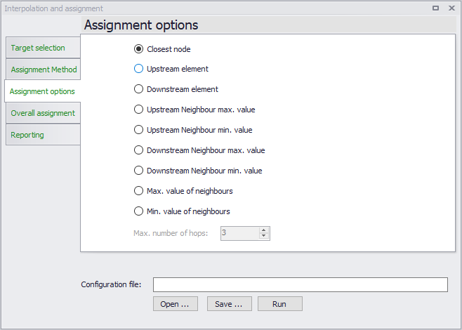
Figure: The assignment options dialog
For the ‘Assign from network neighbours’ assignment method, the following assignment options are activated to define how the assignment is to take place:
- Closest Node - This will use the node that is closest to the one being assigned to. This option is only relevant if both target and source are nodes.
- Upstream Element - This option will assign from the upstream element (upstream/downstream is as defined by the GIS geometric network and may differ from the actual flow direction (which may not be constant).
- Downstream Element - This option will assign from the downstream element (upstream/downstream is as defined by the GIS geometric network and may differ from the actual flow direction (which may not be constant).
- Upstream/Downstream Neighbour Max. Value - These two options will scan the connected network neighbours upstream/downstream and use the maximum source value found as data source. Example: for assigning ground level and diameters.
- Upstream/Downstream Neighbour Min. Value - These two options will scan the connected network upstream/downstream neighbours and use the minimum source value found as data source. Example: for assigning invert levels.
- Max. Value of Neighbours- This option will scan the connected network neighbours and use the maximum source value found as data source.
Example: for assigning groundlevel and diameters. - Min. Value of Neighbours - This option will scan the connected network neighbours and use the minimum source value found as data source. Example: for assigning invert levels.
For the ‘Linear interpolation along network path’ option, the following assignment options are activated:
- Maximum number of hops. This allows you to control how many network 'hops' the interpolation will search for a value. The search continues until the max number is reached or a non-null value is found. When the value is set to 5 or higher it may cause instability (particularly in looped networks). A value of 0 means that only immediate neighbours are taken into consideration. Large values may be time consuming if a large number of features are selected for update.
- Path selection method - The linear interpolation method interpolates between two features along the network. At junctions between multiples links, several paths can be selected (affecting which source features to interpolate from), and this option is used to control this selection. The method 'Select shortest link' will select the shortest link upstream or downstream the node, to define the path along which to interpolate. The method 'Select largest pipe area' will select the pipe with the largest flow area upstream or downstream the node. The following limitations apply to this 'Select largest pipe area' method:
- If two pipes with the same flow area connect to the same node, the tool will select the one with the smallest length
- Other link types than pipes are ignored, i.e. the path only select pipes
- Pipes with missing flow area values (typically diameter) are ignored
- In collection system networks, natural channels are ignored
- In SWMM networks, only circular and closed rectangular conduits are supported by this method.
In the example below, values in Node_2 will be interpolated between Node_1 and Node_3 with the method 'Select largest pipe area', and between Node_4 and Node_3 with the method 'Select shortest link'.
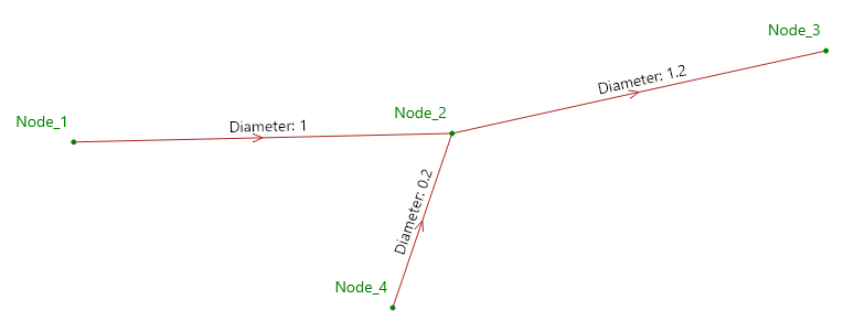
Figure: Interpolation path selection options
Overall Assignment
In this step of the workflow, as shown in the figure below, you can control which features are taken into account for the assignment operation.
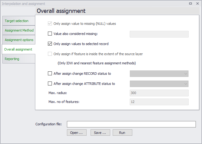
Figure: The Overall assignment dialog
The following options are available:
- Only assign value to missing (NULL) values - means that features that already have a value in the target field will not be updated. Removing this tick mark will overwrite any existing attribute values.
- Only assign values to selected records - this means that only records that are selected before the wizard was started are taken into consideration for updates.
- Only assign to features inside the extent of the source layer - this option prevents the tool from extrapolating outside the boundaries of the source layer when looking for the closest feature or when doing IDW interpolation.
- After assign change RECORD status to - this option changes the status of the modified records (e.g. nodes), by applying the predefined status selected from the list. This is the main status for the record (e.g. the nodes), which is typically found in the 'Description' tab.
- After assign change ATTRIBUTE status to - this option changes the status of the modified attribute (e.g. ground level), by applying the predefined status selected from the list. Every record is defined with multiple attributes, and this option will change the status for the updated attribute only. This attribute's status (e.g. the node's ground level) is found in the Property view, under the 'Status' menu.
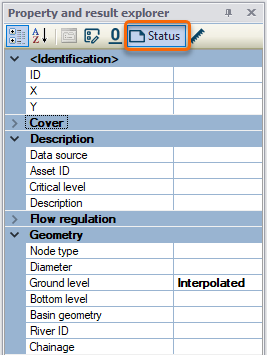
Figure: Accessing the attributes’ status
Tool Execution
To update the model with the interpolation/assignment, click on “Run”. The last section ‘Reporting’ gives a summary of the features that have been updated.
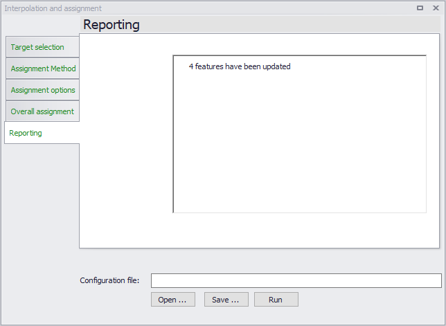
Figure: The report dialog
Configuration File
As with other MIKE+ tools, it is possible to save the tool setup configuration ('Save' button located near the bottom of the tool). A configuration file is created in a *.xml format and can be reused later (using the 'Open' button).